This is the multi-page printable view of this section. Click here to print.
Half Scale Pinball
- Speaker Panel | Half Scale Pinball
- Building a Test Stand | Half Scale Pinball
- A fiberoptic DMD?! | Half Scale Pinball
- Ball Trough | Half Scale Pinball
- Ball Ejector Testing | Half Scale Pinball
- Return Lane | Half Scale Pinball
- Slingshots | Half Scale Pinball
- Testing Inductive Probes | Half Scale Pinball
- Half Scale Pinball
Speaker Panel | Half Scale Pinball
Sight and sound
I’ve made a lot of small updates to the pinball machine since my last post but let me first introduce the new speaker panel I’ve designed.
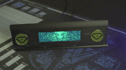
The bolts at the bottom won't be visible once the artwork is applied to the acrylic cover
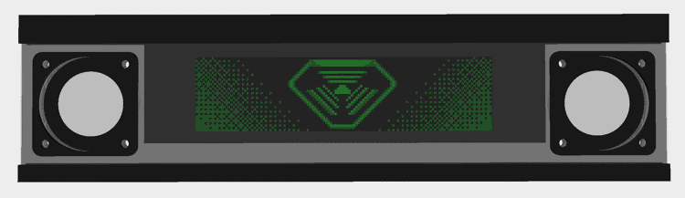
The panel houses the 1920x480 display I mentioned in my DMD post as well as two 2" speakers embellished with green mesh and TriOptimum logos.
The panel secures into the cabinet with M4 studs and thumb-nuts allowing for easy removal
As an aside, if you’ve only played the System Shock Remake or System Shock 2, the TriOptimum logo may look a bit wrong to you; however, that actually is how it looked in the original game. Interestingly, you can find media released with the original game that does show the more modern logo but I chose to use what you actually see while playing.
The original logo from one of the game's cutscenes
Panel design
One of the reasons it’s taken so long to get a new post out is that I’ve been working to convert the project from OpenSCAD to FreeCAD for added features. Some of these features, like support for sheet metal bends, were essential to making progress on the speaker panel; however, in FreeCAD, nothing is easy.
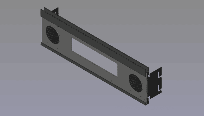
The finished CAD model of the speaker panel
One of the main challenges I faced was just trying to figure out how to make a hexagonal grill for the speakers with the TriOptimum logo overlaid. In OpenSCAD, I’d just use for-loops and the difference operation to “cut” the hexagons out of panel’s profile and the union operation to add back the logo but it’s not that simple in FreeCAD.
The problem I ran into is that FreeCAD’s sketch workbench doesn’t appear to have any way of creating a repeating pattern. Manually sketching each grill hole would take forever and bog down the program so I had to find another solution. Thankfully, someone else already made a tutorial for creating grills in FreeCAD. I had to deviate some to get the results I needed but ultimately, the process boiled-down to the following:
FreeCAD grill tutorial
Disclaimer
I’ve read it’s not good to mix the PartDesign and Part workbenches but this is the only way I knew how to do this and it hasn’t broken on me yet.- Create a master sketch of the speaker panel with all the mounting holes and DMD cutout but no speaker holes
- Create a master sketch of a single grill hole (a hexagon in my case)
- Create a master sketch of the TriOptimum logo I wanted over the grill
- Add dimensions to a master spreadsheet defining width and height of the hole grid as well as how many holes should be present horizontally and vertically
- Create a grill “punch” file which will serve as a virtual hole punch for making the grill
- Create a PartDesign body for the grill grid
- Add a backing-plate which all the hexagons will attach to (since a PartDesign body doesn’t allow disconnected geometry)
- Extrude a single hexagon from the plate near the corner
- Use the MultiTransform operation to first repeat that hexagon into a line across the plate and then again to repeat that line into a grid using the dimensions from the spreadsheet to define the length and occurrences of each pattern (all extrusions must touch the plate or the operation will fail)
- Create a second PartDesign body which will serve as a mask to remove parts of the grid where the logo will be
- Create a backing-plate (again just to ensure all parts of the logo will be connected)
- Extrude a cylinder from the backing-plate the diameter you want the speaker hole to be
- Pocket the logo from the cylinder such that areas you want the logo to show are not solid but do not allow the pocket to go all the way through the plate or the operation may fail if the logo has disconnected geometry
- Create a new Part body and move both PartDesign bodies into it
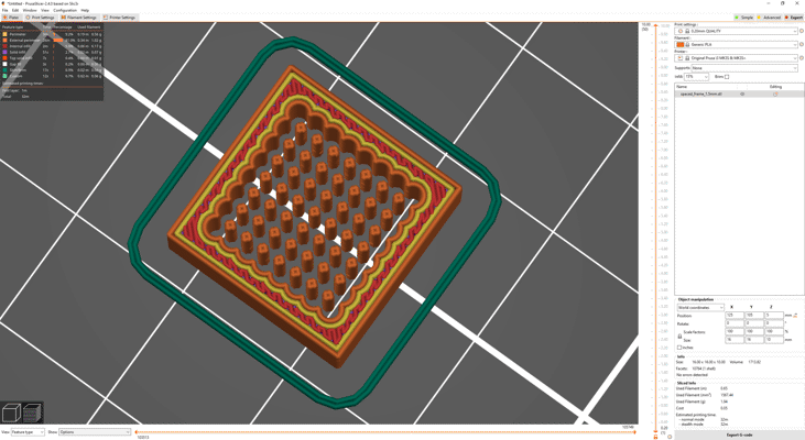
- Perform an intersection of the bodies so that you’re left with the “punch” for the grill
- Remove any shapes from the punch that would produce holes too small for your fabricator to cut by applying a CompoundFilter and setting the Window To value to a number high enough to remove the excessively small shapes
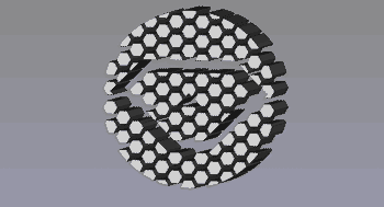
The "punch" for the speaker grills
- Create a PartDesign body for the grill grid
- Create a panel file for the final part
- Add a PartDesign body
- Extrude the speaker panel sketch to whatever thickness your material is
- Add a Part body and move the PartDesign body under it
- Link the punch file and move it to left speaker position; repeat for the right
- Apply a cut operation on the Part body using the left and right punch bodies
- Export the final Part body as a DXF to get the final cutting profile
Yeah… it’s a complicated mess that would have taken a fraction of the time to design in OpenSCAD but to be fair there are many other parts in this design that would be a nightmare to make in OpenSCAD.
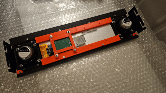
Speakers
Given the size of the display, I only had room for ~2" (50mm) front speakers. That’s not a lot of room to work with but thankfully 2" speakers are a common standard so there’s plenty to choose from. I don’t know much (or anything) about audio but I do like how my Logitech X-140’s reproduce System Shock’s soundtrack so I looked for speakers that sounded similar.
As is a theme for my harebrained schemes, I found some really cheap speakers on Amazon and figured I’d give those a test first. I’ve heard it’s pretty common for a lot of higher priced speakers to actually be poor quality so I figured I’d start from the lowest possible price and work my way up instead of overpaying from the start.
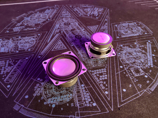
At only $4 each, these are surprisingly not terrible
And honestly… I didn’t think they sounded that bad… or at least not when I had them on my desk. They had absolutely no bass at first when I had them propped up on their boxes but sitting them on my desk greatly improved their sound. Thing is though, I know mounting them in the backbox would help but I don’t think it would have quite the same effect as sitting them on a wooden desk. I assumed I’d need speakers that had more bass on their own if I wanted them to sound good.
I should mention at this stage I was determined not to buy a dedicated subwoofer for a few reasons:
- I couldn’t find a subwoofer small enough to fit under the playfield (even 6" subs are quite tall)
- My cabinet isn’t meant to have legs so even if I could mount it in the bottom, it would be pressed against the table
- The cheap amp I bought to test with was only 2 channel
Anways, based on some reviews I decided to order two different speakers from Dayton Audio in the hopes that one would have better bass: the PC68-4 and the DMA58-4. Both models sounded very similar to me but I felt the DMA58-4 was slightly closer to what I wanted; however, neither solved the bass issue.
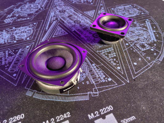
The PC68-4 (left) and the DMA58-4 (right)
It might be possible to get small speakers with good bass but I decided to go ahead and get the smallest subwoofer I could find along with a better amp. Unsurprisingly, this greatly improved the sound. Even the original cheap speakers sounded much better with the sub; however, I decided to stick with the DMA58-4s.
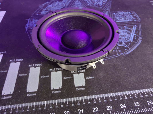
The sub may look small on camera but it's going to be a challenge to fit into such a small cabinet
Having good audio is great and all but it won’t do me any good if I can’t fit the speakers in the machine. Like I mentioned earlier, I can’t really put the sub in the bottom like a full size machine since it would interfere with mechs on the bottom of the playfield.
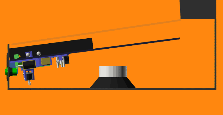
I don't have any mechs in the center of the playfield yet but if I did the speaker would interfere
Mounting the sub in the back clears the playfield; although, I may regret this later when I need to install the power supplies. I’m hoping the sub will sound okay in the back.

The sub's magnet is pretty close to the back of the playfield so I may need to move it down some to not pull the ball
New test stand
The last test stand I designed worked but I had some issues with it:
- The playfield kept falling out when I moved the stand
- There wasn’t anywhere to mount the backbox electronics
- The front extrusions weren’t held on very well
- It wasn’t easy to adjust its width
- Overall it just felt flimsy
Using most of the same parts and some new brackets, I rebuilt the stand into something much more workable. The new stand is more rigid and adds hooks to the playfield so it can’t fall out anymore. The new design also gives me extra room at the back to mount electronics and room at the top for the DMD.
I'm confident this thing has more bolts in it than the average fighter jet
Intro animation
The fancy new speaker panel wouldn’t do me much good without something to display on it which is why I’ve been practicing my pixel art and working to reimagine the game’s intro cutscene as a DMD animation.
It’s still a work in progress but the idea is to have SHODAN’s into speech play while alternating between sequences like this and the high-scores.
Text-to-speech
If you’ve ever played the original System Shock then you’ll know SHODAN isn’t the only voice of Citadel station. There is a second artificial male voice used for things like countdowns and the reactivation of medical chambers. This second voice, commonly called the Citadel PA, is very clearly computer generated.
Why does this matter? Well while I do plan on using voice lines from SHODAN as callouts, the selection of lines is fairly limited and recording new lines in her iconic style would be difficult. That’s why I want to determine how the PA’s voice was made so I can recreate it for most pinball-specific lines.
To start, I listened to every interview I could find with the game’s composer, Greg LoPiccolo, for any clues on the voice’s design. Greg stated that he used SoundDesigner on a Mac to edit the audio and noted that it was very limited having no DSP effects and only being capable of cutting, pasting, EQ adjustments, and pitch shifting. Unfortunately, Greg never specifically mentions what speech synthesizer he used for the PA voice throughout any of the interviews I found ([1], [2], [3], [4], [5]) but this was a good start.
Given Greg had very limited editing capabilities at the time, I’m assuming he used the output of the speech synthesizer mostly as-is which should make it easier to narrow down. I started looking into which synthesizers were available before 1995 since the CD release of the game (the version with voice lines) released December 1994. So far, I’ve found the following:
- SAM - 1982
- DECtalk - 1984
- MacinTalk - 1984
- Dr. Sbaitso - 1991
- MacinTalk 2 - 1994
MacinTalk 3
MacinTalk 3 appears in many searches as being far more capable than its predecessors but what little information I can find seems to indicate it didn’t release until 1995. While it’s not unheard of for a game studio to have early hardware/software access to incentivize making games for a platform, I’m not convinced that would include something like an unreleased version of MacinTalk.I took an example line from the game and tried to reproduce it using emulators for each of the synthesizers. Below are the best examples I could come up with for now:
Based on this test, I’m fairly certain that DecTalk was the synthesizer used. The pronunciation, inflection, and speed match the original line far closer than others. That said, you may have noticed that I was being very specific about the version of DecTalk I tested and there’s good reason for that. I’ve found each version of DecTalk sounds very different; additionally, some of the settings that work in one build just sound like noise in others. Just listen to the default 4.61 and 4.62 samples back-to-back and you’ll hear a difference. Unfortunately, I can’t find any other versions of DecTalk to test with so 4.61 build 109 is the closest I have.
DecTalk has tons of settings and I haven’t really even begun trying to adjust the pitch or EQ of its samples so I still have a long way to go before I can replicate the PA voice. Despite the effort required, I’m confident I’ll get a better result from this approach than trying to train an AI text-to-speech model on what few PA lines there are; although, I have considered using machine learning to try and find the optimal combination of DecTalk, EQ, and pitch settings but for now that seems like it will take more effort than it’s worth.
Other updates
Pushing buttons
Something I forgot to mention in the last post were the flipper buttons I’m using. While these look like standard arcade buttons they’re much cooler. Pinball machines typically use leaf switches which have a smooth actuation while most arcade switches use clicky microswitches; unfortunately, the switches made for pinball typically have a large leaf switch attached to the back that takes up too much space and I don’t like clicky arcade switches.
The switches I’m using are special though. They look like arcade switches but they actually contain an integrated leaf switch. This makes them compact without compromising the switch feel. I got these at Ultimarc but they may be carried elsewhere.
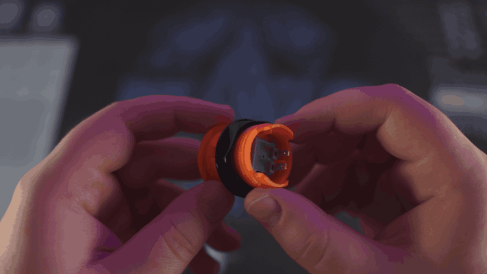
Here you can see the terminals of the integrated leaf switch
I haven’t decided the final switch color for the machine so I bought a pair of every color offered.
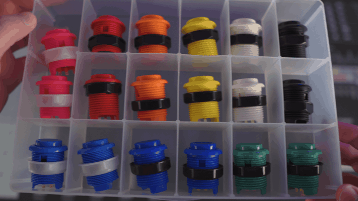
Some of these colors are giving me ideas for future machines
Polycarbonate
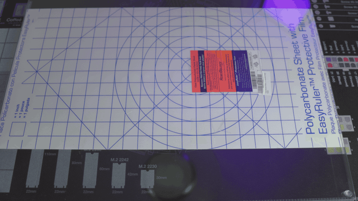
I mentioned back in my post about slingshots, that I intended to cover my playfield with a thin layer of polycarbonate to cover the holes for the inductive probes. Without the polycarbonate, the ball would skip over these holes so I needed to get some for playtesting.
Now unfortunately, I don’t have the tools (or the room for the tools) to make precision cuts in polycarbonate and I couldn’t find any company willing to machine it either. Companies like SendCutSend will machine thicker plates no problem but nobody appears to offer the thinner sheets I need. I figured my best bet for getting accurate cuts in the poly was to get a template made from a different material and use a plunge router to trace it into the poly. That said, I didn’t want to invest in a template at this stage so I decided to just order some precut poly from Amazon that happened to match the dimensions of the playfield and make the rest of the cuts by hand.
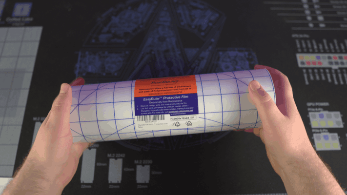
The 12"x24" roll of polycarbonate I found on Amazon
That was a mistake. The poly I got from Amazon shipped rolled and refused to lay flat even after being left under a weight for a week. I’ve never had to flatten poly before but the resources I initially found said the best approach is to sandwich it between two plates of glass and apply light heat for a short period. I had a feeling this wouldn’t end well but I was curious so I decided to order a couple cheap glass plates and a heated mat to test it out.
The polycarbonate between two glass plates
Why a heated mat? Well, I figured it would provide fairly even heating and be easier to keep at the target temperature. In a shock to no one, I cheaped out and the mat I got could only just barely reach 97F. I even tried insulating it from the air with a thick towel but the highest temperature I could get was 102F. With this low temperature, the poly was getting warm but it just wasn’t enough to do anything.
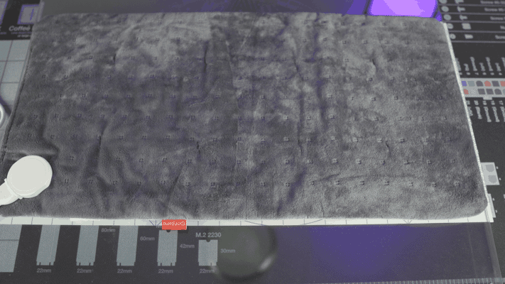
It's hard to describe just how sketchy this heating mat feels in person
At this point, I decided to go for broke and got out the hot air gun. Well, I actually tried using a hair dryer at first but it was too smart for its own good and refused to heat up the polycarbonate at close range. My sketchy hot air gun had no such issues though.

You can see just how warped the poly was with the top sheet of glass off
Despite my hot air gun being able to melt low temp solder, it still couldn’t heat the poly enough to relax it. I could get sections to lay somewhat flat if I applied heat for several seconds in one spot but it wouldn’t stay down even if I quickly pressed it between the glass and allowed it to cool under pressure.
I’m really not sure why this didn’t work. Honestly, I was surprised applying direct heat with the hot air gun didn’t outright melt the plastic (I was nearly touching the tip of the gun to the plastic most of the time). All I can think is maybe the plastic and the glass were just too much for the little gun to saturate.
At any rate, I decided to move on and just order poly from a different supplier. The new sheets came from TAP Plastics and while they did arrive rolled, they did lay mostly flat after leaving them sandwiched between the glass for a few days. Turns out buying supplies from reputable places saves time. Imagine that.
All that said, I don’t think I’m going to use the poly after all. In the FAST Pinball Slack group, some people brought up how polycarbonate sheets will actually expand with heat from the machine and cause the surface to warp. I’m also still not confident in my ability to cut the precise holes I need plus I may have found a better solution to my slingshots.
“Micro” switches
I was randomly searching Amazon, as you do, and came across something I’ve never seen before. Extremely tiny leaf switches.
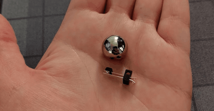
5/8" pinball for scale
Size isn’t everything though. What really matters is actuation force as the mini pinballs don’t even weigh enough to actuate a keyboard switch. And…
They’re perfect!
These little switches are easily actuated by the weight of the ball and even seem to resist vibration. I have no idea what these switches were designed for but I found even more variants of them on AliExpress and eBay with different mounting hole orientations. With these new switches, I’m re-evaluating the design of the slingshots and rollovers to use these instead. If I can get rid of the inductive probes, that would completely negate the need for a polycarbonate layer over the playfield.
Flipper redesign
Speaking of redesigns, one of the main reasons I switched to FreeCAD was to make designing the new flipper mech easier and I cannot stress just how much it’s helped. I haven’t quite landed on a final design just yet but I do have a couple interesting prototypes.
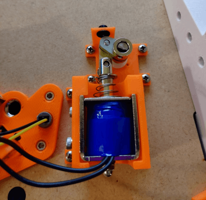
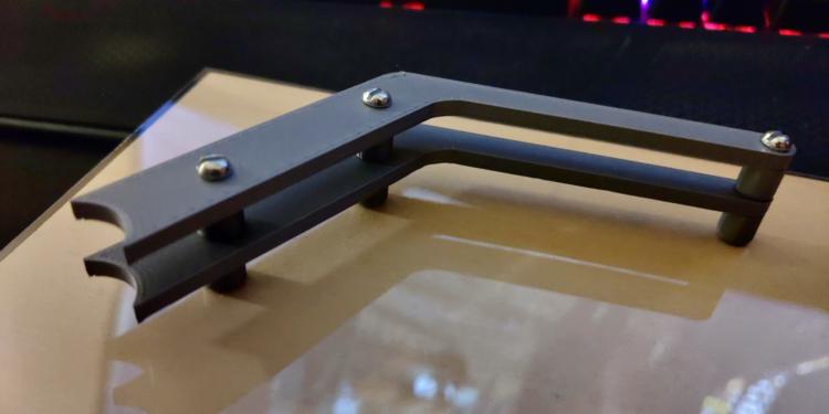
The first of the prototypes printed and installed
There’re a few big changes with this new design. For starters, the entire linkage is metal with stainless steel crank arms and a brass link. Less obvious is the custom machined rotary shaft with flats to drive to the flipper and crank arm. I’ve also switched to a much smaller solenoid and added a rubber backstop.
That’s sort of where the good things end with this design though. I chose to use a flat to connect the crank arm and shaft despite knowing that full-sized machines just clamped onto a round shaft to allow for adjustment. Suffice to say, I needed that adjustment. I’ve found that even slight variations in placement and spring tension result in the flipper bat being misaligned with the return lane. In this prototype, there is no way to adjust the resting position of the bat aside from cutting a new crank arm.
Furthermore, I want to switch the design over to tension springs. It’s my understanding that compression springs wear out faster and provide less consistent force compared to a tension spring. Tension springs are also less likely to bind up.
Finally, I need to add an end-of-stroke switch to the mech so the software knows when the flipper bat is fully rotated. This is critical because the solenoid will overheat if given full power for too long. To allow players to hold flippers up, the coil needs to switch to low power once the bat has reached the end of it’s stroke. While you can use a timer to guess how long the bat should be given full power, that won’t account for if the bat starts to drop from a direct impact and would be a pain to tune.
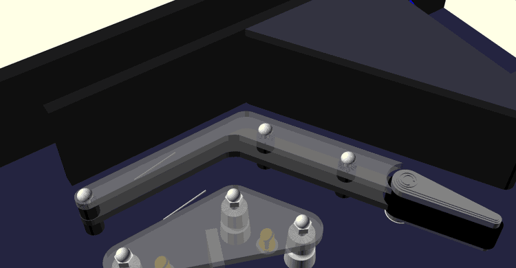
As for the second prototype, I’ve been wanting to raise the flipper mech off the bottom of the playfield so I could use the space under it for a secret feature I’m working on. To do this, I designed a custom metal mounting bracket based on its larger counterpart.
Left is an off-the-shelf flipper bracket, right is my mini bracket
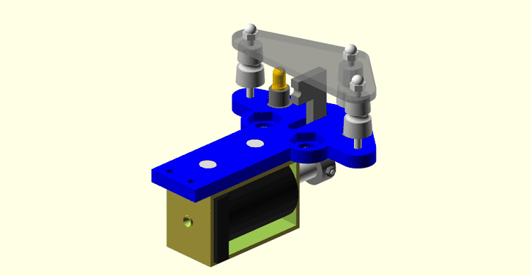
It’s not perfect (in fact I can’t even mount the mechanics to it because I screwed up hole placements) but raising the flipper mechanics off the wood will allow me to place the fasteners I need under the mech.
Going FAST
For my earlier tests, I was just using an Arduino with a relay shield to control my solenoids. That worked for simpler mechs but my flippers require PWM so I needed a better solution. Around that time, FAST Pinball’s boards were back in stock so I picked up a Neuron, smart power filter board, I/O board, and some opto boards. These should give me just enough I/O to run my playfield’s lower-third. Even better, this means I can finally start using Mission Pinball Framework for my game rules instead of writing temporary C++ programs.
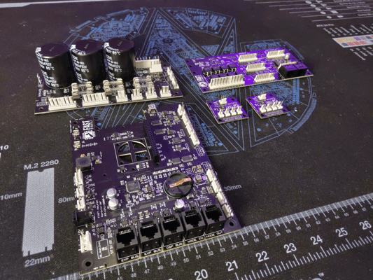
Hopefully all these boards will fit into the final cabinet without too much trouble
Burn it all down
With all this progress, you might be surprised to hear that I need to redo most of it.
Up till now, I’ve been using 6mm MDF for the playfield. I knew MDF wouldn’t work as a long-term solution so my plan was to eventually switch to 6mm Baltic birch plywood for the final playfield; however, I’ve been rethinking that decision for some time. I just don’t think that 6mm birch will be enough to withstand the weight of all the mechs or offer enough material for the screws to hold onto.
After putting it all together, I’ve made the painful decision to redesign the machine to use 1/2" Baltic birch plywood instead… which means the flipper, auto-plunger, ball trough, ball ejector, and slingshot all need to be redesigned. It’s painful but I think having more material to mount mechs into will pay off in the long run.
Building a Test Stand | Half Scale Pinball
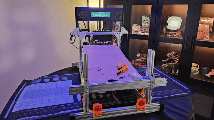
On my way to a playable machine
These past months, I’ve been working to get the lower-third of the machine in a playable state so I can finally playtest. Thankfully, I’m nearly done as all I have left is the redesign of the flipper mech. The only problem is I didn’t have a way of propping the playfield at the correct angle or holding its sidewalls in place.
With full size machines, the playfield dimensions are at least somewhat standardized so you can borrow a cabinet from another machine or build your own from plans online but I’m not making a standard playfield. I do intend to build a cabinet for my machine but my playfield dimensions could still change so I don’t want to waste the time or money on the cabinet. Instead, I wanted to build something adjustable.
Aluminum extrusion FTW
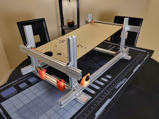
I figured my best option was to build the test stand from aluminum extrusion. It’s relatively cheap, available precut, and reusable. I spent a few days in CAD and came up with this design.
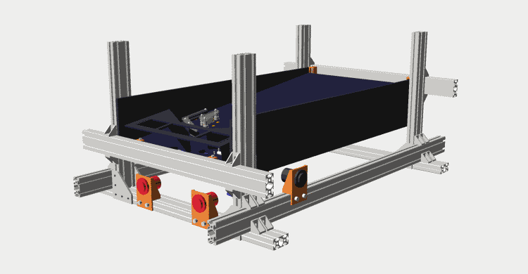
This isn't how you'd normally join extrusions but doing it this way lets each side slide in/out to fit the playfield
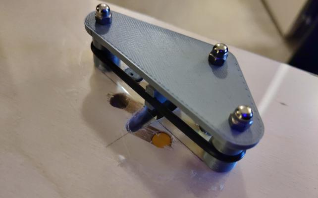
Now, extrusion isn’t a precision component. The beams can be warped and bowed (they are after all the product of forcing molten aluminum through a die). Thing is, even if the extrusions were perfect, there’s no guarantee my table or floor are. To compensate for that, the playfield is resting on four adjustable carriages for levelling.
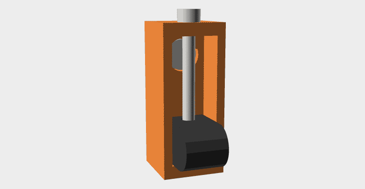
Each playfield support consists of an M3 bolt as a lead screw and a carriage with heatset insert that engages with it
Assembly
One hour and 96 bolts later and I have the stand assembled
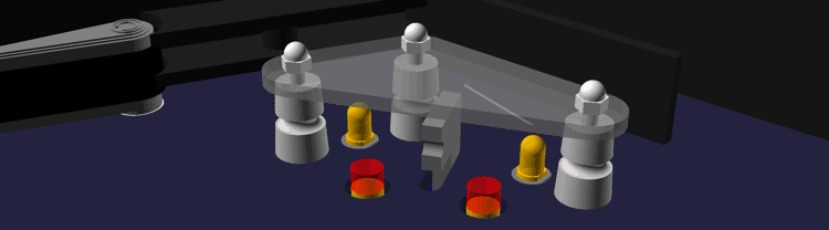
Assembly went smoothly for the most part but there was one unforeseen problem. For the extrusions supporting the playfield, there are plenty of plates and brackets designed to join extrusions whose channels are parallel but I couldn’t find anything meant to join extrusions with perpendicular channels. What do I mean? Well take a look at these renders.
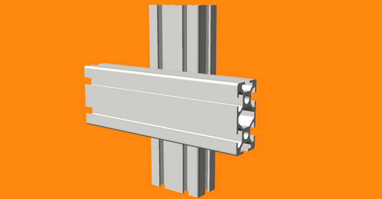
This is how I want to join my extrusions
Now, you wouldn’t normally join extrusions like this; however, joining them the normal way would require cutting them to exact sizes and defeat the purpose of the stand. Joining them this way allows for excess extrusion so I can slide the joints closer/further apart to accomidate the playfield.
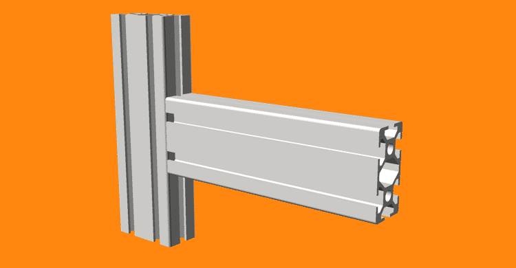
But this is how extrusions are intended to be joined
But wait, what about those little corner brackets in the picture? Well, there in lies the problem. You see, those brackets actually have little tabs on bottom meant to align them with the channel. Unfortunately, those tabs are spaced too far apart to fit in the channel sideways so for one of the perpendicular extrusions it’s not actually making contact with the flat part of the bracket.
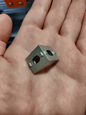
Note how the tabs are thin enough to fit in the channel one way but are too far apart to fit the other way
While this does affect how precise the joint angles are, that isn’t really the biggest problem here. What I soon discovered was these tabs dig into the sides of the extrusion and effectively lock it in place even when you loosen the bolts. This makes it much more fiddly to adjust the dimensions of the stand than I had intended.
I’ve since thought of a few other ways I could have constructed the stand to avoid this but it’s good enough for now that I’m fine with it as is. Also note, I did find some different brackets that don’t have the alignment tabs; although, they may not work for this application since they are designed to attach from the ends not the channels.
If you get nothing else from this post, just take this as a word of caution in case you plan on building something out of aluminum extrusion as well. Hackaday has a great article on how to properly join and constrain extrusions if you’re interested.
Playfield
You may have already noticed the fancy new lasercut playfield. It’s a bit barren and this is far from a final layout (I don’t even know yet if I’ll be using the standard “Italian” design) but it will at least let me mount all the mechs I’ve designed for testing.
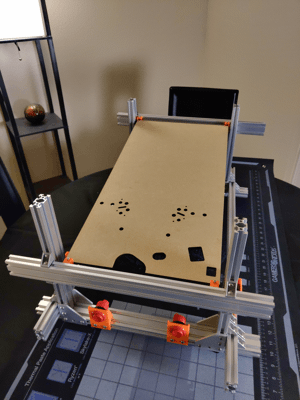
The lasercut playfield fits nicely in the new stand
A fiberoptic DMD?! | Half Scale Pinball
…but why
You, being a sane and reasonable individual, are probably wondering how I could possibly think it was a good idea to build a fiberoptic panel for my pinball machine’s DMD. Frankly, I don’t even have a great answer to that so I’m going to mix things up this post and just present this whole ordeal in the order of events that led me here. I realize I went pretty far off the rails with this one so bear with me.
Design requirements
This all started when I got thinking what kind of display I wanted for the machine. While pinball has used many display types over the years, I wanted a display capable of showing bitmap animations which left me with two options: a dot-matrix display (DMD) or an OLED/LCD screen.
System Shock is fairly low resolution by modern standards so I felt the look of larger pixels would suit it better and while I knew it was possible to emulate the look of a DMD on a screen, I still preferred the look of a real DMD’s rounded pixels. So problem solved, right? Just buy a small DMD and… this is where things started to get messy.
Most pinball DMDs have an aspect ratio of 4:1 with a resolution of 128x32 pixels. Modern DMDs are typically constructed from two 64x32 pixel modules commonly used for digital signage. Unfortunately, these off-the-shelf modules are not, to my knowledge, available in pitches less than 2mm (pitch being the center-to-center distance of each pixel). That may seem small on paper but consider that a 128x32 display with a 2mm pitch would still be 256mmx64mm (~10"x2.5"). Again, that may seem small but my entire backbox is only 14" wide and I still have to fit speakers on either side of the display. Not to mention a full size display is just 320mmx80mm (~12.6x3.1") so it’s not even that much smaller. Clearly, I needed to find a better solution.
A full size display technically fits but something tells me the game wouldn't sound quite right without its front speakers!
Half resolution panel
The “obvious” next question was: since everything else on the machine is half-scale, why not halve the DMD resolution as well? On paper, this solved a lot of problems since a display with exactly half the resolution would fit perfectly in a half-scale backbox; however, as is often the case, ideas that sound good on paper don’t always work so well in practice.
The fundamental problem with this approach is that a pinball’s DMD already has a soul-crushingly small resolution of just 128x32. Aurich on Pinside already did a great job explaining why this resolution is so limiting so I won’t rant about it here but just looking at the image below should make it clear just how little information you can fit in this resolution with any semblance of theming.
Even on a full resolution DMD, the TriOptimum logo from System Shock barely fits
Now halve that already small display to just 64x16 (a resolution barely larger than some Tamagotchi models) and you’re left with something unusable for the kinds of animations I want (more on those later).

The font used throughout System Shock's levels is barely recognizable at a 64x16 resolution
Custom panels
If I had to pick a moment where things really started to spiral out of control, it would be here. Hellbent on not using a screen, this is where I checked my sanity at the door and started down the path of building a custom DMD.
8x8 matrices
The first idea that came to mind was to buy a bunch of 8x8 pixel matrices and arrange them into a custom display. The problems with this approach became apparent right away though as I couldn’t find anybody selling these matrices in a size anywhere near small enough. Just using the bog-standard size, I would only be able to achieve a resolution of 32x8.
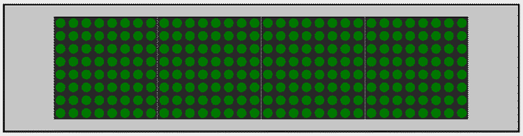
The black outline represents the size of a half-scale DMD. Unfortunately, these 8x8 matrices are so big that only four fit in the space.
Through-hole matrix
Since prebuilt panels were too big, I figured I could just wire up a panel from scratch using through-hole LEDs. I had seen a video a while back from Ben Heck about the custom DMD he built for his Bill Paxton machine which gave me confidence this would work; however, I soon learned the smallest through-hole LEDs I could get (1.8mm) were still too big. Upon re-watching Ben’s video, I also realized his matrix wasn’t the full resolution so I lost confidence that I’d even be able to wire a full resolution display manually.
Surface-mount matrix
Since through-hole LEDs were too big, I turned my attention to SMD LEDs. There are a few different sizes of SMD LEDs but the smallest I could find were so called “NanoPoint LEDs” at a size of just 0.65mmx0.35mm. But wait, didn’t I just say I couldn’t manually solder the 4096 LEDs my panel would require? Yes; however, my plan was to have the LEDs pre-installed on a custom PCB through a service like PCBWay. That is at least until I totaled up the cost. The LEDs alone would be over $500 plus another $300-400 for automated assembly. I’m not opposed to shelling out money for this project but nearly $1k for a display is just wasteful!
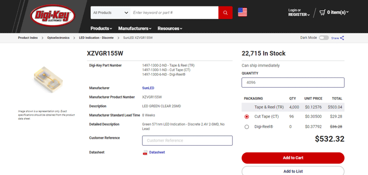
The cost of 128x32 (4096) NanoPoint LEDs from DigiKey
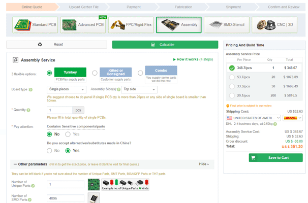
The cost to have PCBWay assemble a board with 4096 SMD components
Cost wasn’t even the main issue with this approach. Regardless of LED size, there are still physical limits on how close I can pack them on a PCB and still be able to route their power and ground traces. There may have been a way to make it work but I don’t have the PCB design experience (or any for that matter) to pull it off.
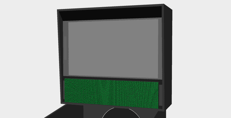
Fiberoptics
Of all the issues I mentioned above, one problem was common to them all: the physical limitation of how closely LEDs can be packed together. This got me thinking… if I can’t fit the LEDs any tighter, could I instead route the light from a larger panel to a smaller display? I briefly considered using lenses but that idea was soon squashed by another: fiberoptics.
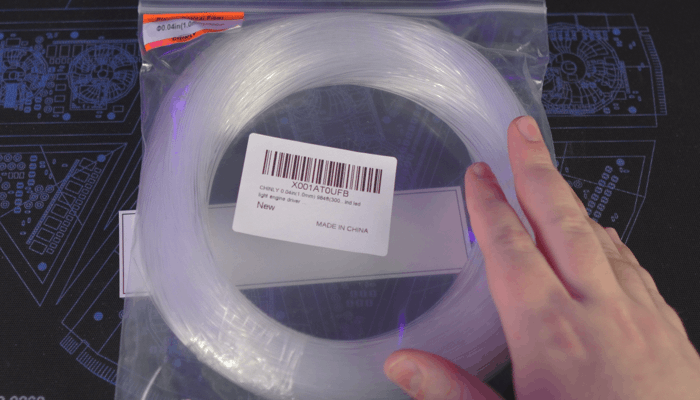
Bundles of fiberoptic filament like this are readily available on Amazon in many different lengths and diameters
I did some quick searching to see if anyone else had attempted something similar and sure enough two others had already uploaded videos of their designs: elliotmade and Dr. Tõnis Gadgets. With that validation, this seemed like a good idea; however, I couldn’t decide on how to build the display. My two thoughts were to either use a larger diameter filament and simply pack the filaments together for larger pixels or to use a smaller diameter filament and build a grid to space the dots out (like what the YouTubers had done). For testing, I decided to use one of the 8x8 matrices I bought earlier to prototype each approach.
Packed filaments
My plan for the “packed filament” approach was to build a square frame which would hold the filaments tightly together. I hoped the filaments would naturally arrange themselves into an 8x8 grid if there was no free space to go anywhere else. I was concerned some filaments, particularly in the middle of the matrix, would end up closer or further back and thus darker than others so I also built a bezel which would hold a thin piece of polycarbonate to the frame acting both as a display surface and a hard stop to push the filaments to. For this test, I chose to use 1.5mm filament as this was the largest I could go without a 128x32 display becoming too big.
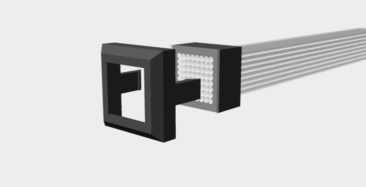
Exploded view of the assembly
On the LED side, I simply created a part which would snap onto the 8x8 matrix and allow the fibers to be press-fit into holes over each LED. I wanted to ensure the light from one LED couldn’t travel to a different fiber so I designed the part to fit flush against the panel but recess the fibers back to minimize light polution.
Note how the filaments don't go all the way through the mount. My thought being this would help prevent light bleed.
Unfortunately, the problems with this design were severe enough I couldn’t even test it. Right away, I found the filament did not fit into the frame I designed. I thought at first the filament was either larger than advertised or my printer undersized the part; however, neither of these were the problem. The issue turned out to be the filament, which hard been shipped as a roll, was trying to remain curved and thus taking up more space. I found I could just barely fit the filaments into the frame if I applied enough force but in doing so the filaments were not aligning into a grid like I had hoped and were instead forcing the frame apart leaving gaps in the display.
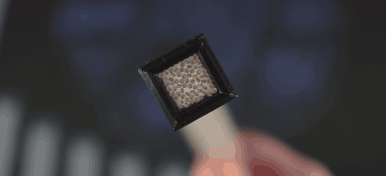
Despite my best efforts, I couldn't get the filaments to align into a grid
I probably could fix this with enough time and patience but seeing as how I was already encountering issues in an 8x8 display, I felt it best not to attempt with a larger panel.
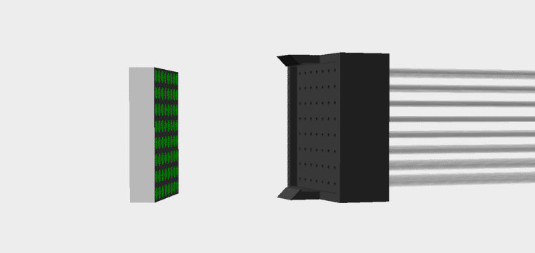
Spaced filaments
For my second test, I borrowed most of the design from the previous experiment but changed the frame to be a solid piece with a grid of holes. I used 1mm filament for this test and initially designed the part with a hole pitch of 1.5mm to result in the same size display as the previous experiment.
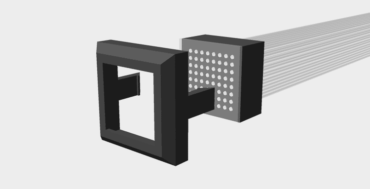
Exploded view of the assembly
This didn’t work out as planned either though. My printer has a 0.4mm nozzle and despite my best efforts there just wasn’t any way I could slice the part and have it come out correctly at this resolution.
With some tinkering, it was possible to get the slicer to accurately slice the thin walls; however, my printer just couldn't handle it
In desperation, I tried increasing the hole pitch to 1.9mm and reducing the final resolution to only 100x25 dots to maintain a similar size. Thankfully, this did slice without error but my problems weren’t over yet. The holes in the frame came out inconsistent. Some were too large and others too small. Rather than spend an eternity tweaking the hole sizes and slicer settings, I felt it would be best to just drill out all the holes to 1.5mm and glue the filaments in place.
This was a mistake.
It took me four days of gluing to finally complete the display. Not only did I have to wait a couple hours between each row to allow the glue to dry (accelerant couldn’t reach the glue inside the holes) but it took ages to find which filament needed to go where. I knew I didn’t technically need to line the filaments up on the DMD and display sides since any mismatch could be corrected in software but I’m not a fan of fixing hardware problems in software.
While the display face may look messy from the glue, I suspect some window tint could hide the marks without significantly affecting the lights
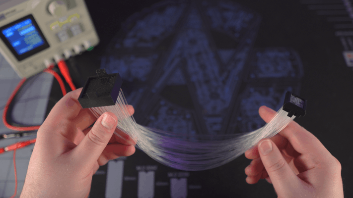
The final assembly was done and to my delight it actually worked quite well save for two problems. The first being some filaments pulled out slightly from the frame while drying resulting in a few pixels which are noticeably darker than others. This could probably have been fixed with more QC but the second problem was more fundamental.
While obvious, the dark pixel isn't the only problem here. Look closely and you'll notice there is a fair bit of light bleed to adjacent pixels.
I had completely overlooked that a bundle of the filament would no longer be flexible so the two ends of the display could not be moved. What’s more, the curve of the filaments forced the assembly to contort into a curve as well making it much harder to work with. Like most issues I described, there is almost certainly a way to get around this in the final machine but at this point I was exhausted, defeated, and was frankly bored of this who endeavor.
Compromise
While none of the approaches I tested worked, I don’t feel the time was wasted. I learned a fair bit along the way and I’m sure I can find some other uses for the fiberoptics in the future. That said, I still need a display.
I decided to finally do the reasonable thing and resolve to just use an OLED panel but I still wasn’t happy with how how emulated DMDs look. I got to thinking though… what if I had the display render square pixels and just put a mask over the screen to make them round.
The pixels look a bit off here since the mask is raised above the surface of the screen
Frankly, I’m embarrassed I didn’t think of this sooner. It seems so obvious in hindsight. I thought at first the mask layer might be hard to manufacture given the hole size and spacing but I got an online quote to machine it from metal for around $350. That’s certainly not cheap but it’s not completely unreasonable either. I do have a couple other ideas though. I figure I could try with vinyl; although, I worry it will be difficult to apply without distorting. I’m also curious if a blank PCB would work given PCB routing is typically very precise and quite cheap.
256x64 panel
That just leaves one last problem, the OLED panel.
I’m usually skeptical of panels advertised for use with Arduino and Raspberry PI boards as they’re often controlled via slow interfaces that limit the refresh rate; however, I did find a 256x64px OLED panel with options for a parallel interface and even natively supports 16 levels of greyscale per-pixel (though I only plan to use 4).
Like the other pre-made displays I mentioned earlier in this post, the only problem with this model is it’s size… except in this case it’s a bit too small. The pixels of this display are only 0.53mm so the entire display is just ~135x34mm (~5.3"x1.3"). That’s a fair bit smaller than the 160mmx40mm (~6.3"x1.6") of a true half-scale display and the 192mmx48mm (~7.5"x1.9") size I was aiming for with the fiberoptic panels. Even with the speakers on either side, I think this panel would look a bit too small; although, I may get one to try out anyways.
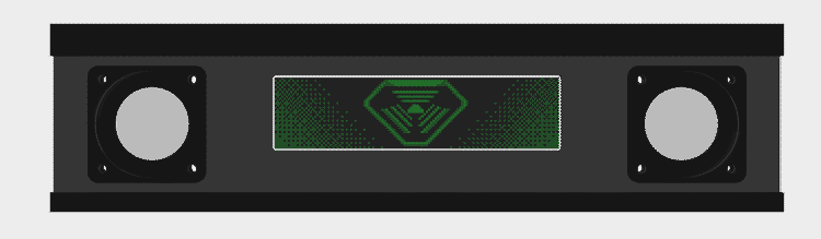
What do you think of the square speaker grills? They're still a work in progress but I'm worried they make it look like the front-end of a jeep.
High resolution panel
Another option would be to just buy a replacement panel for a phone, tablet, or similar and find a controller to drive it. I believe this would be the cheapest option by far given mobile displays are a commodity; however, finding one wide enough to fill out the space without being too tall will be a challenge. There is also no guarantee that I’ll be able to find a display driver capable of running it.
With some searching, I eventually found another promising option. 8.8" (~223mm) 1920x480 displays are apparently common in automotive applications and you can even buy some that natively accept HDMI. Size is once again a problem here though as the 217mmx54mm (8.5"x2.1") area is a bit bigger than I’d like. I could hide the extra pixels behind the bezel but it encroaches on the speakers at that point.
With this X-ray, you can see just how much of the screen would be cropped and why the speakers have to be moved to accommodate it
Animation sneak peek
Ultimately, I’m going to put more display testing aside for a bit and focus on other parts of the machine. That said, I want to leave you with some ideas I’ve been working on for potential DMD animations.
Disclaimer: None of these images are final. I don’t claim to be great with pixel art so I may even commission someone to remake them later.
TriOptimum Logo
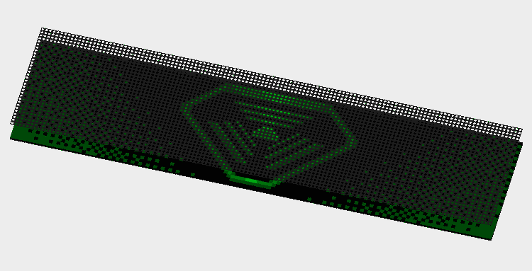
The TriOptimum logo I’ve shown throughout this post is meant to be part of the attract mode. My intent is to periodically play a DMD-rendition of System Shock’s opening video. The green text of the hacker’s laptop is a big part of the reason I want a green DMD.
The gradients are just here to fill in space in the screenshot. They won't be there in the final animation.
Fonts
System Shock makes use of several different fonts; however, my favorite is the retro-futuristic font, StopD, used to label each floor of the station. I plan on using this font for any large text in the game. Interestingly, System Shock uses a customized variant of the font (or perhaps an older version) as some letters differ slightly (for example, the Y). For this reason, I’ve gone through screenshots of the game painstakingly re-creating their version of the font pixel-by-pixel.

I couldn't find an example of a W in System Shock's levels so this one is based on the original StopD font. More tweaking is needed to make it match the style of the others.
SHODAN
One of the creepiest occurrences in the original System Shock is how SHODAN’s face will periodically fade into view on displays showing static. I’ve always loved that detail and thought it would be cool if I could do something similar on the DMD. I think the effect works best when the player just barely catches it so my plan is to have the face rarely fade in behind the player’s score but dissappear before they have a chance to get a good look at it.

In game, SHODAN appears to have a wide smile on the in-game displays; however, I'm fairly certain this is just a side-effect of down-sampling her usual stoic expression to the lower resolution displays. Either way, I like how creepy her smile looks and decided to mimic it for my game.
CAD Files
By the way, I’ve published STLs to Printables and the CAD to GitHub if you really want to try making one of these fiberoptic displays as well; although, I really can’t recommend it for anything more than an experiment.
Ball Trough | Half Scale Pinball
It’s working! (finally)
I know it’s been a while since my last post but I have a good reason… Borderlands 2 is a lot longer than I remembered. No but seriously I’ve actually made a lot good progress since my last post and now have a working ball trough, ejector, and auto-plunger to show for it.
My hope was to complete prototypes of the ball trough, slingshots, flippers, auto-plunger, and lanes so that my next post could feature them all working together. Obviously, that didn’t happen. I kept running into problems here and there that pushed a full test out. A few of the problems still aren’t fully resolved but I felt it was best to show what I have now before waiting for everything to be final.
So what problems remain? I’m sure you didn’t ask but I’m going to tell you anyways:
- The current flipper design is bulky and likely to fall apart after moderate use
- The auto-plunger needs to operate at 24v which means I need to redesign the flippers to work at that voltage as well
- I designed for lane walls that were only 1/8" thick and I’m realizing now they’re too thin to screw into from the edge for mounting
I’ll talk more about those issues toward the end but for now let’s think positive and talk about that fancy new ball trough.
Design process
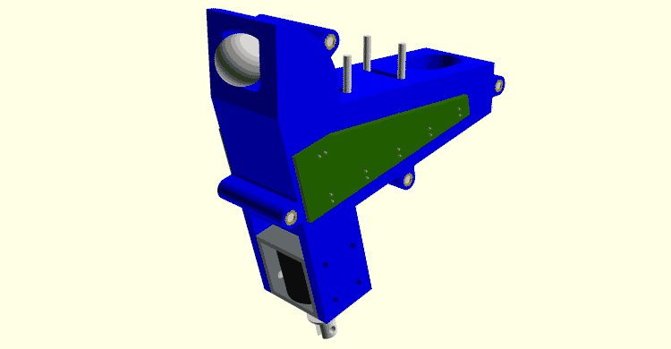
The ball trough assembly in all its vaporwavey goodness
This is actually the third iteration of the ball trough design. The original plan was to model the ball trough and ejector as one piece but make the ejector chute/scoop a separate component. I eventually realized there was no reason the two components couldn’t be combined for easier assembly.
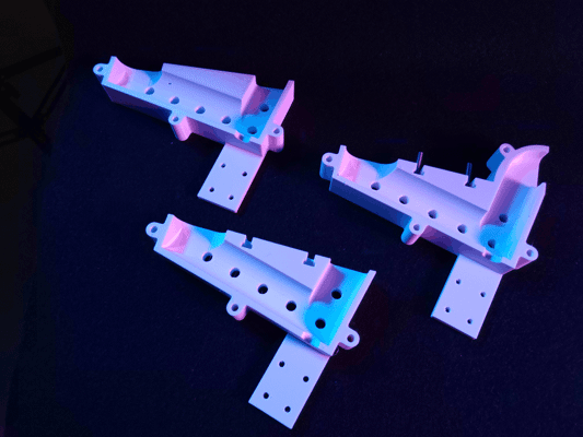
The progression of trough designs from first (left), second (bottom), to current (right)
I also revised the playfield mounts in the second and third revisions. The first revision had heat-set inserts pressed into the top with the intent being to bolt into them through the playfield. While this would have worked at first, I was concerned the heat-sets would work their way out over time. This wouldn’t have been a concern if I had pressed the heat-sets in from the bottom of the part but there was no easy way to do that without compromising functionality. An easier fix was to just switch which side had the nut and which had the bolt. The new design features T-slots allowing four M3 hex bolts to be held captive in the assembly. The threads of these bolts pass through the playfield from the bottom and the whole assembly is secured from the other side using washers and lock nuts.
That’s not to say heat-sets have no place in this design though. The final revision added heat-sets to one half of the assembly and counterbores to the other allowing the two halves to be bolted together more securely and without protrusions on either side. This was done to give me more clearance for the circuit boards later (more on that in a bit). During final assembly I intend to use thread locker on the heat-sets to ensure the bolts can’t back out from vibration (being careful of course to not get any on the plastic).
Updated solenoid
You don't want to know how long it took to render this image thanks to all the hacky Boolean operations I used to model it
Something that may not be obvious from the pictures is I’m no longer using the McMaster-Carr 70155K121 solenoid I tested back in February. While the 70155K121 was strong and much smaller than the first solenoid I tested, I managed to overlook one critical detail. The plunger on that solenoid was so long that it would have stuck out the bottom of the machine by half an inch.
Let this be a lesson to check dimensions in CAD before committing to a design 🤦♂️
Silly mistakes aside, the ball ejector is now using the much cheaper T Tulead ADD06190484. I don’t know why I never thought to check Amazon for solenoids before but this model is cheaper, stronger, and smaller than any solenoid I previously tested. At only 12v, this model is perfectly capable of ejecting balls from the trough even when all 5 balls are loaded or when two become jammed in the ejector chute.
Speaking of jams…
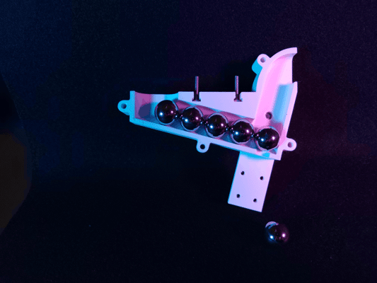
Behind each ball is a hole for an infrared LED. The opposing side of the assembly has matching holes for photodiodes.
Just like it’s larger counterparts, my design uses five pairs of infrared LEDs and photoelectric diodes to detect how many balls are currently in the trough. The LED and diode pairs form an invisible beam at each ball position that is broken when a ball sits between them. The software simply needs to count how many photodiodes are blocked to determine how many balls are in reserve.
If a ball ever fails to eject or otherwise falls back into the chute, there is a good chance that it will become stacked on the next ball in the trough. An additional LED/diode pair is placed in the ejector chute to detect this condition. When this photodiode is blocked for more than a few hundred milliseconds, the software knows a malfunction has occurred and can either attempt to unjam itself or enter maintenance mode.
For the moment, I’m just hooking up jumper wires to the sensor pairs for testing. I would have liked to use proto-board; however, the LEDs are spaced 5/8" apart (the ball diameter) so the spacing doesn’t quite line up for standard pitch PCBs. Once the machine is nearing completion, I’ll send off for custom PCBs; additionally, I’ll add holes to the model for M2 heat-sets to mount the boards to.
WIP Auto-plunger
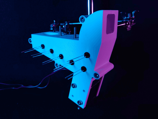
I'm not planning on adding a manual plunger to the System Shock pinball machine but I've designed the kicker arm to allow for one in future projects.
I created a rough working prototype of the auto-plunger but there is one big issue with the design. The kicker arm is only attached to the solenoid plunger using an M2 nut and bolt. While I could make the nut captive, the bolt will likely still become loose over time. I’d like to use a clevis pin instead; however, the smallest clevis pin I can find is 3mm in diameter but the hole in the plunger is closer to 2.8mm. I could try widening the hole but I’d rather just find a new solenoid model that’s more compatible and potentially smaller.
One thing I like about this design and have started incorporating into other mechs is how the solenoid is mounted. Screwing into the solenoid through the bracket does make replacing the solenoid more difficult but it makes for a much more stable mount. As an additional bonus, having the bolts held captive between the playfield and bracket ensures they can never work themselves loose even without thread locker.
If you’re familiar with how auto-plungers are designed for full-size machines you may have noticed there is no room for a kicker ball sensor with the solenoid mounted directly under the playfield. I didn’t have room on the right side of the shooter lane for an optical sensor either and I’d like to avoid capacitive sensors as I don’t like the look of sensor plates or conductive tape. I also considered making the kicker arm out of two insulated conductive plates and using the ball to complete a circuit between them but I decided to avoid custom metal parts for the moment. Ultimately, I’ve chosen to just use an inductive probe. Beneath the apron is a LJ8A3-2-Z/BY probe that pokes through the left shooter lane. With correct placement, I’ve found this probe to be very reliable at detecting when the ball settles on the kicker arm.
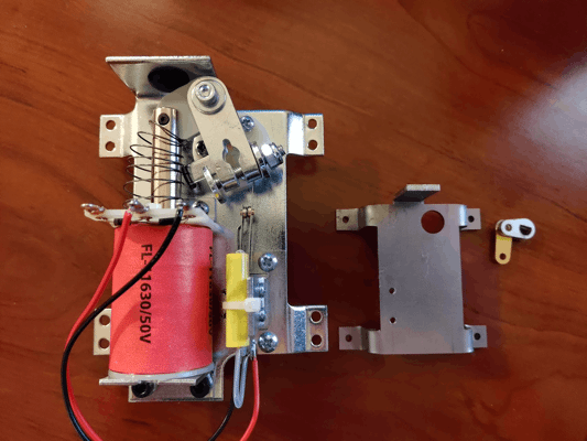
Revisiting the flipper
It's not easy to spot in the first picture but the flipper shaft passes through a precision flanged PTFE bushing just like it would on a full-sized machine
I’ve had a working flipper design since before I started this blog; however, experience designing other mechs and changes to the machine as a whole have made me rethink this design. For starters, the current design is unnecessarily bulky. This is largely due to the body being interchangeable between the right and left flipper assemblies; however, part of the bulk is due to the solenoid being mounted sideways and could be trimmed down by using the same mounting technique as the auto-plunger.
Parts availability and tooling is also somewhat of an issue. It’s not pictured above but the flipper bat and crank are reinforced by a 4mmx4mmx50mm shaft made of steel bar stock. The only 4mm bar stock I could find was made of hardened tool steel and wasn’t available in the length I needed. I was able to cut one shaft down to size with great difficulty but that’s not an endeavor I ever want to repeat. I’m currently investigating the options Misumi has for ordering custom rotary shafts as they look to have all the features I need (albeit at an eyewatering price).
Similar to my concern with the auto-plunger, I’m not happy with the linkage being attached using M2 nuts and bolts. Unlike the auto-plunger, the nut and bolt head are held captive; however, they do still become loose after a few shots. Switching to clevis pins should solve this issue but requires that I use a solenoid with a wide-enough hole to accommodate the pins I have in addition to making the linkage parts wider.
I also want to remove the skate bearing for simplicity sake. The bearing serves two purposes in the current design 1) to stabilize the crank shaft and 2) to prevent the crank body from sliding off the steel bar running through it. I don’t think I actually need the bearing to stabilize the shaft given it is already constrained by a fairly long precision PTFE bushing in the playfield; furthermore, the crank sliding off shouldn’t be a problem if I add a set screw.
This design isn’t all bad though. I was initially very worried that I wouldn’t be able to find flipper rubber in the right size or with many color options. As luck would have it, “Grifiti Band Joe” silicone bands ended up being the perfect size and came in several different colors. Newer prints of the flipper also include a rubber backstop to prevent damage to the linkage when the flipper resets.
Next steps
Once the flipper redesign is complete I’ll send off for a laser-cut playfield for an integration test. I also need to replace the relays in my prototype with MOSFETs so I can PWM the coils.
Just to level-set, all that’s a bit of a ways off though as I’m working on some upgrades to my 3D printer to support ABS printing and those upgrades will have it out of commission for a time. I also want the first full integration test to be well recorded so I’ll be spending longer than usual on its video.
Ball Ejector Testing | Half Scale Pinball
Ball trough design
On most pinball machines, a mechanism called the ball trough stores the balls not currently in play. Balls enter the trough through the playfield drain and are returned to play via a mechanism that ejects them back up to the shooter lane. There are several different styles of ball trough but I’ve decided to use the more modern design that requires only a single solenoid (pictured below).
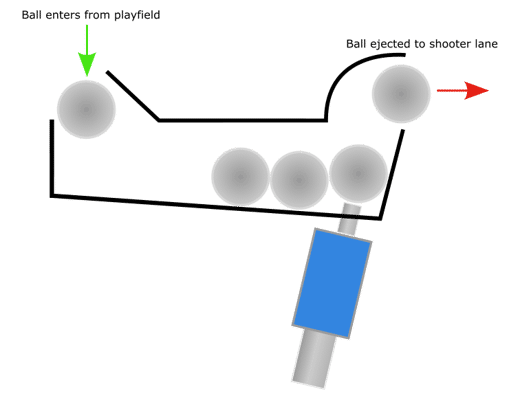
Side-view sketch of how a modern ball trough works. Not pictured are the physical or optical sensors used to detect how many balls are currently stored or if the ejector has jammed.
I like this design for two reasons: it’s dead simple and leaves more space above the playfield under the apron which I plan on using for a special feature I’ll talk about more in a future post. The main drawback to this approach is it takes considerably more space under the playfield due to the solenoid placement and the fact that most push solenoids have plungers that extend fairly far out the back.
Solenoid testing
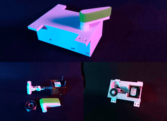
Given the limited space inside my pinball machine, I wanted to see just how big of a solenoid was required to eject the ball. To test the solenoids, I built a scoop roughly as tall as that needed in the final design and brackets to attach each solenoid to it. I ran each solenoid at an increasingly higher voltage starting at 12v until it was capable of ejecting a 5/8" (~15.87mm) ball with reasonable force.
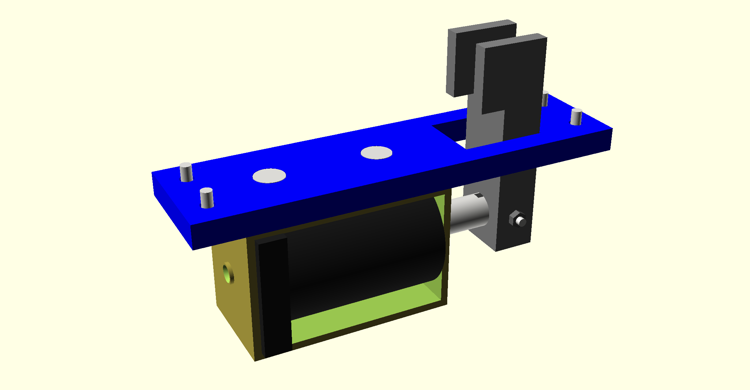
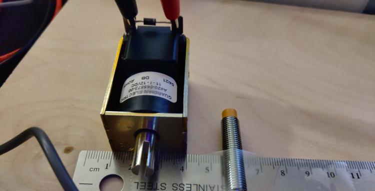
Guardian Electric A422-064104-04
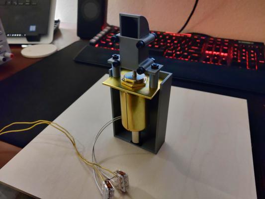
Testing the A422-064104-04 solenoid
The first solenoid I tested was the Guardian Electric A422-064104-04. This thing is a chungus but I picked it because I thought I would need at least a 1" (25mm) stroke length to get the ball up the chute (spoilers: I didn’t). I should also note that up to this point, I had been buying all my solenoids exclusively from Allied Electronics & Automation because they seemed to carry more models than other suppliers. In hindsight, this was a mistake as their stock mostly caters to industrial applications not as constrained by size.
While the solenoid did work, I had to run it at 18v to eject the ball with reasonable force and its size wasn’t even the worst of its problems. It’s expensive, awkward to mount, and heavy. I mean really heavy. I was genuinely concerned mounting it under the playfield without supports would cause the surface to bow. This is what finally pushed me to check other suppliers for smaller models.
Something I’m only just realizing as I type this is I accidentally bought the continuous duty version of this solenoid when I really should have bought the intermittent duty variant (the A422-064104-03). Intermittent duty solenoids are generally stronger than their continuous duty counterparts given the former is allowed time to cool between uses and can therefore pass more current. Ultimately, I don’t believe this would have changed my opinion of this series though given they’re still too large.
McMaster-Carr 70155K112
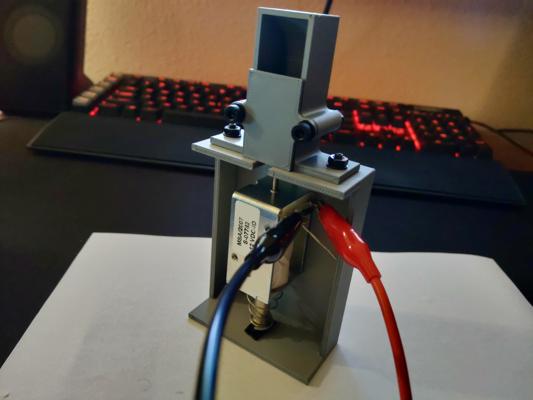
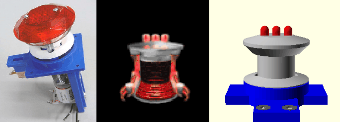
Testing the 70155K112 solenoid
The second solenoid I tested was the McMaster-Carr 70155K112. This model is what I ultimately decided to use in my design and for good reason. At only 12v and with a 1/2" (12.7mm) stroke length, this solenoid was capable of ejecting the ball with no issues. The benefits don’t stop there either. It’s lightweight, short, easy to mount, comes with a return spring, and includes a second plunger type.
This model does cost an eye-watering $40 per unit but I can look the other way given just how perfectly it works in this application.
As an aside, you may have noticed the scoop was redesigned for this test. I intended to reuse the scoop but that didn’t work out in practice as the bolts holding the original together conflicted with this solenoid’s bracket. I could have just removed the lower two bolts but I also wanted test printing the scoop with a flat back as the rounded back of the original didn’t turn out well.
In case you’re wondering, I never throw away unused/broken parts like the old scoop design. I store the unused parts, brims, supports, etc. by filament brand, type, and color in the hopes of one day recycling them with a filament mulcher/extruder.
McMaster-Carr 70155K121
The McMaster-Carr 70155K121 is essentially just the continuous duty variant of the 70155K112 I previously tested. The only reason I decided to test it too was to see if the ball could still be ejected with a lower force solenoid (spoilers: it could not). Most of the smaller solenoids I could find from other suppliers were weaker than this so I decided to stop my testing here.
Next steps
Now that I’ve chosen a solenoid, I can start designing the ball trough assembly. I expect this to take a while given the geometry will be relatively complex compared to my previous assemblies but that’s not to say I won’t be posting in the interim. I’ve got a few other projects on backburner that I’ll be sharing until the ball trough prototype is ready.
Return Lane | Half Scale Pinball
The prototype
I’ve completed a first draft of the return lane assembly; although, it’s not fully tested at this time. The problem is I can’t really test the lane without having the side wall and slingshot on either side to verify the ball behaves as I’d like. For the moment, I’ve just printed and installed a single lane on a test board.
The left return lane assembly installed on a test board
The top plate of the assembly is largely cosmetic so for the final design I intend on making it more “blocky” to better fit with the 90’s DOS shooter theme of the original System Shock. I also plan on constructing the bottom plate from metal to reduce wear. I’m considering building the top plate from clear acrylic; however, I don’t have room under the playfield to add lights under it so that may be a waste.
The right return lane assembly in the playfield render
Challenges with designing in OpenSCAD
For prototyping, I heavily leverage OpenSCAD’s Boolean operations to quickly create complex shapes; however, there is no direct way to create fillets. This posed a problem for the return lane prototype as the inlane has a concave fillet where the lane divider joins the flipper return lane.
There are a few ways to accomplish a concave fillet in OpenSCAD but they each have their drawbacks:
- You can programmatically draw the curve using the 2D subsystem but this is made difficult by the lack of a built-in Bezier curve library.
- You can subtract a circle from the corner but this gets more complex when the joint isn’t 90 degrees.
- Clever use of the offset module can produce fillets but they will be applied to the entire object.
- You could draw the part in vector art software, export to SVG, and import into OpenSCAD; however, the part will no longer be parametric.
The dimensions of the machine are bound to keep changing as I refine my designs so I opted for the simplest route of simply subtracting a curve from the lane using a hard-coded ellipse. It’s not elegant and it’s not robust but it does get the job done quick so I can move on to more important assemblies.
Each colored section represents a different primitive I union'd or difference'd to create the final part profile
For the final part, I’m considering writing a Bezier curve library to let me draw the curve directly in OpenSCAD. I know Bezier curve libraries already exist for OpenSCAD; however, I’m pretty opinionated with how I structure my scad files so I’d rather write the library myself to keep everything consistent. I also have bigger plans down the road to build a dependency manager for OpenSCAD so it would be helpful to have some of my own libraries I can test with.
Slingshots | Half Scale Pinball
Testing
Last post I said I’d be working on the in/out-lanes next but I finally got all the parts in to run a full test on my slingshot assembly and just couldn’t wait. The video below demonstrates the assembly with a few different general illumination colors and explains how it all works.
For this test, I just used an Arduino 4 Relays Shield and some simple code to fire the solenoid for 1/10th of a second when either sensor triggered. I also wrote in a delay forcing the solenoid to remain off for at least one second after firing to give it time to cool down (not that it gets that hot from the short burst anyways). I don’t plan on using relays to drive the solenoids in the final machine as most will require PWM signals but the Arduino is sufficient for prototyping.
Overall, I’m really happy with how the assembly turned out. That said, this is by no means the final version as there are a few quirks I need to work out.
Areas for Improvement
Unnecessary Return Spring
In the video, you can see a return spring around solenoid plunger. Theoretically, this shouldn’t be needed as the slingshot rubber can also reset the plunger; however, I found it was needed in the prototype as the slot for the slingshot actuator is slightly too short causing the actuator to get stuck without the spring.
The only reason I want to remove the spring is because it’s reducing the solenoid’s power by a fair bit. I was originally running the solenoid at 15v; however, the addition of the spring required I increase the voltage to 18v to kick the ball with the same force. Running the coil at a higher voltage isn’t ideal as it both puts more wear on the coil and requires that I run all coils at the higher voltage as well (since I do not want multiple coil voltages in the machine).
Wobbly LEDs
To make the LEDs easily replaceable, I designed custom quick-change sockets to accept standard 5mm LEDs. These sockets are great for prototyping but they don’t grip the leads tight enough resulting in the lights flickering when the solenoid kicks. This is largely because the sockets are really just holders for 2-pin Dupont connectors and the connectors I have aren’t particularly strong.
Additionally, the Dupont connectors are only friction-fit into the sockets and do fall out over time. This could be fixed with some hot glue but I’m still considering other options such as different connectors.
Deadzones
The prototype uses a pair of LJ8A3-2-Z/BY inductive probes running at 5v to detect the ball (see my previous post for more technical details). The probes are compact, easy to use, and easy to mount; however, they have a fairly small detection radius which leaves quite a few deadzones along the slingshot. The most egregious deadzone is directly in front of the kicker which means the assembly is unlikely to ever kick the ball with full force.
Unfortunately, I cannot just put another sensor in the center deadzone as the solenoid plunger would block it. I could try mounting the solenoid vertically like on a full-sized machine but even then I doubt I’d have enough space for the probe.
One option I’m considering is to shift the solenoid closer to the flippers thus giving more room for sensors; although, this would require repositioning the lower sensor further up so I’d really only be moving the deadzone. Ultimately, I don’t want to change the sensor positions just yet though as where the ball contacts each slingshot will depend greatly on the upper playfield and may make the deadzones moot (or at least move them).
Testing Inductive Probes | Half Scale Pinball
Background
One of the goals for my half-scale System Shock pinball machine is to include fully-functioning slingshots. For those unfamiliar, slingshots are the triangular kickers located just above the flippers on most pinball machines. The slingshots are designed to kick the ball diagonally up or down the playfield on contact.
This video shows a great closeup of a slingshot in action if you’ve never seen one before:
Designing half-scale slingshots that can kick was actually pretty easy; however, finding a reliable way to trigger them was a whole other problem. On a full-sized machine, the slingshots are triggered by two leaf switches located just behind the rubber ring. The slingshot is activated when the ball deflects the ring causing it to close one or both of the switches. This mechanism works great for an ~80g (~2.8oz) pinball but not so well when scaled down. Even with the softest rubber rings I could find to fit my slingshots (75A), the measly 16.3g (0.57oz) ball I’m designing for just can’t deflect the rubber far enough or with enough force to actuate most physical switches.
My current slingshot design for reference
To put the problem into perspective, the Gateron Clear keyswitch is one of the lightest keyboard switches you can buy at the time of writing with an operating force of just ~0.3N (0.06lb). Even with such a light switch, I would have to stack two of the 5/8" (~15.87mm) chrome steel mini pinballs just to operate it (let alone bottom it out) with the measly 0.16N (0.03lb) of force each exerts under gravity. Obviously, pinballs are going to be subject to more forces than just gravity and you can find a handful of other physical switches with lower operating forces; however, switches with such low operating forces often require excessive actuation distances or are too sensitive to vibration to use in close proximity to solenoids. I do know of one physical switch that can be reliably activated by the mini pinballs; however, that’s a topic for another day and it won’t work in this context anyway.
As I mentioned in my first post, physical switches are far from the only option for detecting the mini pinballs. Ultrasonic, infrared, and capacitive among others are all good candidates but for this post I will focus on inductive sensors. I specifically want to investigate the use of standard industrial inductive probes like you’d find on a 3D printer.
The Probes
There are plenty of inductive probes available from electronics suppliers but I chose to limit testing to two specific models: LJ8A3-2-Z/BY and LJ18A3-8-Z/BX. Why? The main features I like about these models are they’re easy to mount, trivial to interface with, and have flexible voltage ranges. It also helps they happened to show up on Amazon while I was browsing other parts. The main differences between the models are their size and maximum detection range. The LJ8A3-2-Z/BY advertises a range of only 2mm while the LJ18A3-8-Z/BX boasts an 8mm range at the expense of a much larger footprint.
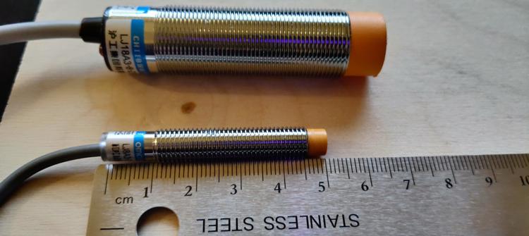
Size comparison of the LJ8A3-2-Z/BY (bottom) and the LJ18A3-8-Z/BX (top)
Both sensors connect using only three wires: power (brown), ground (blue), and signal (black). Questionable wire coloring aside, both sensors are rated for an input voltage of 6-36v and will output a signal when metal is detected in front of the orange cap (or lack thereof in the case of the LJ18A3-8-Z/BX). The maximum range at which the sensors trigger is fixed regardless of the input voltage or at least that’s what the manufacturer claims…
Curiously, I discovered by mistake that running the probes below their rated voltages can nearly double the detection range in some cases. For example, running the LJ8A3-2-Z/BY at only 4v resulted in it consistently triggering at 4mm instead of the claimed 2mm. Unsurprisingly, there is a consequence to running these probes out of spec but it’s worth the tradeoff in my opinion and something I’ll discuss later in this post. I couldn’t tell you if this behavior is common to all inductive probes but I’ve found it to be incredibly helpful and is the main reason I’m writing this post.
Testing Detection Range
Knowing the detection range of each probe changes with voltage, I wanted to run tests to measure the extent of this affect; furthermore, I wanted to measure how far the mini pinball would have to pass over sensor before it was detected.
For testing, I first printed test jigs to align each probe and ball to the same height and let me slide the sensor closer to the ball along a ruler at various horizontal offsets from the ball. I then placed the ball at a known position along the ruler. For each combination of sensor, input voltage, and horizontal offset I would slide the sensor toward the ball until my multimeter showed the sensor had triggered. I would repeat the test a few times to verify consistency then record the distance between the edge of the ball and tip of the sensor.
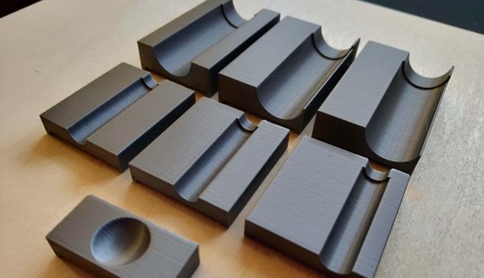
The test jigs
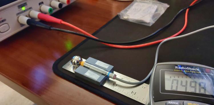
The sensor range test setup
Each sensor was tested at its lowest stable voltage, 5v, and 12v. I opted to not test at any higher voltages as I’m expecting to have power supply rails for 5v and 12v in the final machine but the only rail I’m planning with higher voltage is for driving coils and I don’t think it wise to run sensitive electronics off the same rail.
Each sensor was tested at three horizontal offsets:
- (A) Ball center aligned to the sensor cap’s center (no offset)
- (B) Ball center aligned to the edge of the sensor cap
- (C) Ball edge aligned to the sensor cap’s center
LJ8A3-2-Z/BY
4v was the lowest I could reliably operate this probe. At 3v, the sensor would trigger but not stop once metal left its detection area.
| Sensor Voltage (v) | Horizontal Offset (mm) | Max Detection Distance (mm) |
|---|---|---|
| 4 | 0.00 (A) | 4.0 |
| 4 | 3.25 (B) | 3.5 |
| 4 | 7.94 (C) | 1.0 |
| 5 | 0.00 (A) | 2.0 |
| 5 | 3.25 (B) | 1.0 |
| 5 | 7.94 (C) | - |
| 12 | 0.00 (A) | 2.0 |
| 12 | 3.25 (B) | 0.5 |
| 12 | 7.94 (C) | - |
LJ18A3-8-Z/BX
5v was the lowest I could reliably operate this sensor. The sensor would not trigger at lower voltages.
| Sensor Voltage (v) | Horizontal Offset (mm) | Max Detection Distance (mm) |
|---|---|---|
| 5 | 0.00 (A) | 7.0 |
| 5 | 7.94 (C) | 4.5 |
| 5 | 8.25 (B) | 4.5 |
| 12 | 0.00 (A) | 6.0 |
| 12 | 7.94 (C) | 3.5 |
| 12 | 8.25 (B) | 3.0 |
Testing the Effects of Solenoid Interference
While prototyping the slingshot, I found activating a solenoid close to a probe would cause the probe to trigger. This wasn’t really concerning for the slingshot assembly on its own since I could just ignore the false activation in code but I was worried nearby unrelated probes might also trigger.
To test just how far away a probe would need to be to avoid interface, I first taped each probe to a known position on my ruler. I then placed my test solenoid (model A420-065573-00) along the ruler and fired it at different voltages while watching the probe’s output. If the probe falsely triggered, I would move it half a millimeter away and repeat until it no longer triggered. I repeated this test using the same probe voltages as my previous test and with three different solenoid voltages as I haven’t yet decided the final voltage for the game. Furthermore, I ran this test both with the solenoid facing the probe and with it beside the probe to determine how much the orientation mattered.
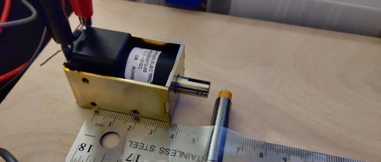
Interference test setup (face)
Interference test setup (side)
For each probe voltage, solenoid voltage, and solenoid orientation, I recorded the maximum distance I found interface as well as the minimum distance I found the probe to be clear of interface. The distance measurements were taken from the faceplate of the solenoid to the center of the probe and from the side plate of the solenoid to the center of the probe.
Hyphens in the following tables indicate configurations were I was unable to get the probe to falsely trigger even when directly touching the side of the probe to the solenoid.
LJ8A3-2-Z/BY
| Sensor Voltage (v) | Solenoid Voltage (v) | Max Face Interference Distance (mm) | Min Face Clear Distance (mm) | Max Side Interference Distance (mm) | Min Side Clear Distance (mm) |
|---|---|---|---|---|---|
| 4 | 12 | 2.0 | 2.5 | 1.0 | 1.5 |
| 4 | 15 | 3.0 | 3.5 | - | - |
| 4 | 18 | 3.5 | 4.0 | - | - |
| 5 | 12 | 1.5 | 2.0 | - | - |
| 5 | 15 | 1.5 | 2.0 | - | - |
| 5 | 18 | 1.5 | 2.0 | - | - |
| 12 | 12 | - | - | - | - |
| 12 | 15 | - | - | - | - |
| 12 | 18 | - | - | - | - |
LJ18A3-8-Z/BX
| Sensor Voltage (v) | Solenoid Voltage (v) | Max Face Interference Distance (mm) | Min Face Clear Distance (mm) | Max Side Interference Distance (mm) | Min Side Clear Distance (mm) |
|---|---|---|---|---|---|
| 5 | 12 | - | - | - | - |
| 5 | 15 | - | - | 1.0 | 1.5 |
| 5 | 18 | - | - | 1.0 | 1.5 |
| 12 | 12 | - | - | - | - |
| 12 | 15 | - | - | - | - |
| 12 | 18 | - | - | - | - |
Results
Ultimately, these tests have given me confidence that undervolting my sensors won’t be a major issue. The increased range (especially for the LJ8A3-2-Z/BY) is extremely valuable and I don’t expect it to be difficult to keep probes more than 4mm away from other assembly’s solenoids to avoid interface. I did find it interesting though that neither probe could be falsely triggered when run at 12v. This leads me to believe the probes are only susceptible to interference when run outside their rated voltage; although, I admittedly didn’t test within the lower end of their specifications.
All that said, the range of the probes is still a concern. Something to consider is these probes are too long to be mounted on top of the playfield which means they’ll have to be mounted under it. Even the best probe configuration I tested can still only detect up to 7mm but my playfield is already 1/4" (6.35mm) thick and that’s excluding the vinyl artwork. I could drill holes into the playfield and mount the sensors flush with its surface; however, it would be difficult to get a close enough fit to not cause the ball to jump when passing over.
The slingshot design with inset sensors. The wider hole is necessary to accommodate the probes' threads. The red cylinders represents the detection area.
This problem bothered me for a few days but I think I finally landed on a decent solution. By overlaying the playfield with a thin sheet of stiff polycarbonate 1/32" (~0.8mm), I can freely drill holes for the sensors in the wood layer while keeping the plastic play surface smooth. This solution comes with a few fringe benefits as well. Applying the playfield graphic under the plastic will help to protect it from the ball in much the same way Mylar film is used to protect full sized machines. This also allows me to hide the sensors if I attach the artwork to the back of the plastic rather than the wood.
If it weren't for the reflection, you'd hardly know there was a plastic layer here. You'll have to excuse the tape and jagged holes. This prototype has been through a lot of iterations and poorly measured cuts.
Next Steps
I worry the sensors may still not have a wide enough radius to detect the ball reliably in game; however, I won’t know for sure until I finish the lower-third and can start play testing. If you’re not familiar, the lower-third is the literal lower 1/3rd of the playfield and includes the major assemblies: flippers, slingshots, the shooter lane, drain, and in/out lanes. I already have working prototype flippers and rough designs for the drain and shooter so next up are the lanes.
Half Scale Pinball
Background
Since 2015, I’ve been working to build a roughly half-scale pinball machine themed after the original System Shock. I got the idea from the various mini-pinball machines built on the Ben Heck Show [1] [2] and from having finished playing the original System Shock around the same time. This whole idea started when I noticed the serv-bots on the medical level closely resembled pinball pop-bumpers. From there, I began to think about how many of the objectives and mechanics in the game could be adapted to modes in a pinball machine.
Pop bumper and Serv-Bot together at last
While the project is far from complete, I’ve decided to start blogging my progress to help anyone else in the community wanting to build their own scaled down pinball machine. The world needs more mini-pinball!
Objectives
From the start, I knew my machine had to be fully featured. To me that means, all of the following mechanisms must be present and they must work more-or-less the same as those found on full sized machines:
- Auto-plunger
- Backglass
- Coin-mech (that only accepts dimes)
- Dot Matrix Display
- Drop Targets
- In/out Lanes
- Kick-out Hole
- Light Strips
- Multiball
- Playfield Inserts
- Pop Bumpers
- Rollovers
- Skill Shots
- Slingshots
- Spinners
- Tilt Sensor
I don’t know how feasible all of these features are but I strive to at least try each one. Additionally, I have a few general goals I’d like to achieve for my own peace of mind:
- Minimal high-voltage wiring
- Consumable components are easily replaceable
- All playfield mechs are designed to be reusable in other games
- Minimal custom PCBs
- Use as many original game assets as possible
- Avoid servos (I just really hate that high-pitch sound they make)
I have a few special features I’m designing in as well but you’ll just have to stay tuned to future posts to hear about those.
Challenges
One of the first and most persistent challenges of building a scaled down pinball machine is the OG buzzkill, physics. As Ben noted in his show, simply scaling down the ball’s diameter by half doesn’t really work all that well as you lose so much mass that the ball becomes uncontrollable. Taking Ben’s advice, I have chosen to use a 5/8" bearing ball as opposed to a 1/2" ball.
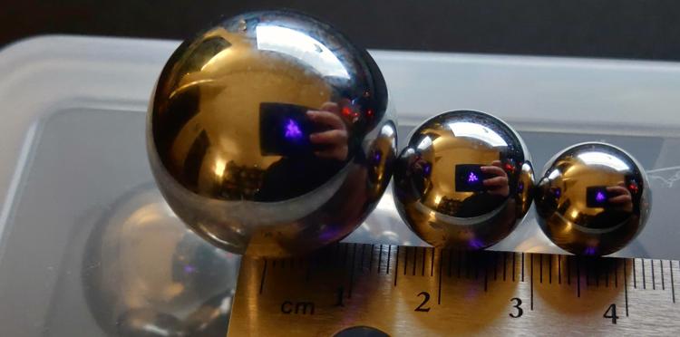
From left to right: 1 1/16" (~27mm), 5/8" (~15.87mm), and 1/2" (~12.7mm) bearing balls
Even with the adjusted diameter, the 5/8" ball just doesn’t have enough mass to actuate most switches. As an experiment, I tried resting one of the mini pinballs on a Cherry MX Speed switch and to my horror it didn’t even begin to depress the switch. As others have demonstrated in their own scaled pinball projects, this limitation does have workarounds but it requires some creative use of alternative sensor types (eg capacitive, infra-red, inductive, etc.).
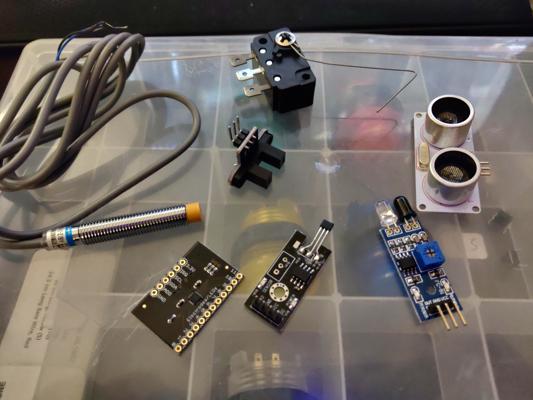
Sensors I've tested thus far including capacitive, inductive, optical, Hall effect, physical, and ultrasonic
Physics isn’t the only problem we’ve got to contend with either. Finding solenoids with enough power and throw to actuate the playfield mechs has been far more difficult than I initially expected. Most higher power and longer throw solenoids are simply too big to fit into a half-scale cabinet and smaller solenoids lack the power or range needed to do anything useful. Thankfully, I’ve found this can be mitigated by overvolting smaller solenoids; although, only time will tell how long the solenoids last being driven at 150-160% their rated voltage.
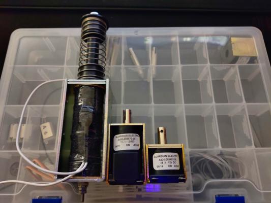
Pictured above are 3 vastly different sizes of 12v solenoids
Development
I personally prefer to work in CAD before making anything physical. I realize this is completely backwards from nearly everyone else; however, I find I just can’t picture the end result I want without drawing it out in CAD first. In a twist that’s sure to surprise some, my CAD tool of choice OpenSCAD. The reason for this is twofold: 1) OpenSCAD’s language really meshes with how I think (pun intended) and 2) Fusion 360 is borked for my Autodesk account and I refuse to make a new account just to fix their software.
In all seriousness, I have used Autodesk 3D modelling and CAD software in the past but being a software engineer by trade I just feel more comfortable writing code. That said, OpenSCAD leaves a lot to be desired (especially in the dependency management front) and I probably would have been a lot farther along by now had I forced myself to use something else. All that’s to say: your mileage may vary.
Current Progress
Unsurprisingly, that laundry list of features, challenges, and my odd choice in toolchains hasn’t resulted in the progress you’d expect to see after 7 years; however, that’s not to say I’ve been slacking either. I’ve made great strides in improving my development workflow with OpenSCAD libraries, tested numerous mech prototypes and sensors, and produced working assemblies for the flippers, slingshots, and drop targets. The screenshots below are renderings of some of the current progress and there will be more to come in future posts.
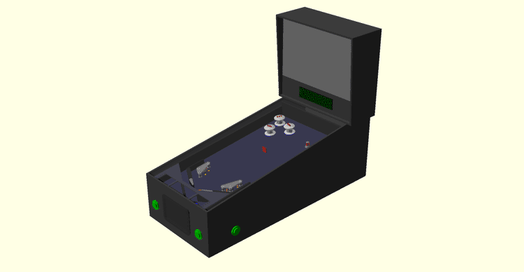
A look at all the designed parts in a mockup cabinet
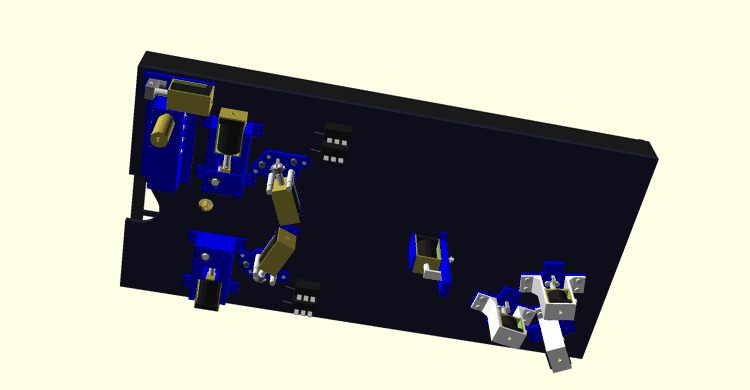
The current underside of the playfield
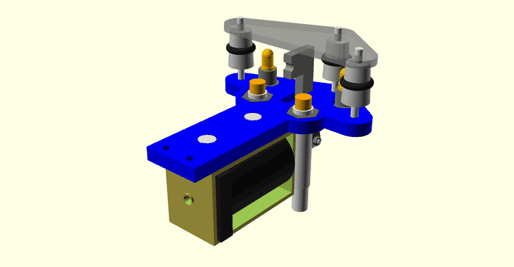
Closeup of the slingshot assembly without the playfield (rubber ring not shown)
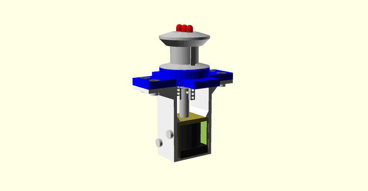
Closeup of the WIP pop bumper assembly
Wrap-up
That’s all I’ve got time to write about for now but be sure to subscribe to my RSS feed so you get notified of my future progress. In the short-term, I’m planning in-depth posts on the mechs built thus far and the challenges I faced designing them.