This is the multi-page printable view of this section. Click here to print.
Blog
- Half Scale Pinball
- Speaker Panel | Half Scale Pinball
- Building a Test Stand | Half Scale Pinball
- A fiberoptic DMD?! | Half Scale Pinball
- Ball Trough | Half Scale Pinball
- Ball Ejector Testing | Half Scale Pinball
- Return Lane | Half Scale Pinball
- Slingshots | Half Scale Pinball
- Testing Inductive Probes | Half Scale Pinball
- Half Scale Pinball
- Game Jams
- A surreal racing experience for GMTK Jam 2025 | InsomnaKart
- I made a rail shooter for Kenney Jam 2025 | Maximum Voltage
- I failed Scream Jam 2024 | Negative
- I made a game for Scream Jam 2023 | Consignment
- Rivermod
- Replacement Score Camwheels
- LOD-ing in OpenSCAD
- Mapping the Ishimura
Half Scale Pinball
Speaker Panel | Half Scale Pinball
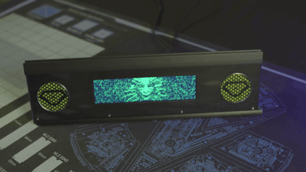
Sight and sound
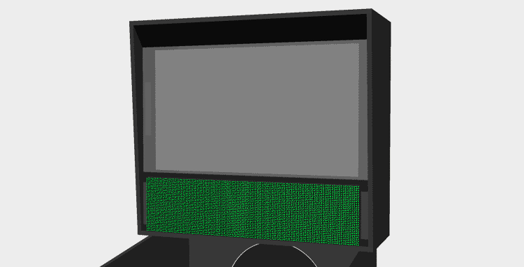
I’ve made a lot of small updates to the pinball machine since my last post but let me first introduce the new speaker panel I’ve designed.
The bolts at the bottom won't be visible once the artwork is applied to the acrylic cover
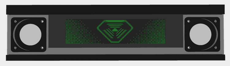
The panel houses the 1920x480 display I mentioned in my DMD post as well as two 2" speakers embellished with green mesh and TriOptimum logos.
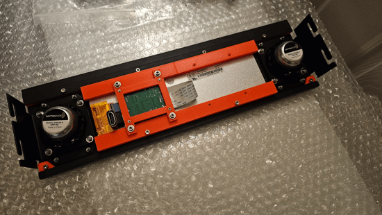
The panel secures into the cabinet with M4 studs and thumb-nuts allowing for easy removal
As an aside, if you’ve only played the System Shock Remake or System Shock 2, the TriOptimum logo may look a bit wrong to you; however, that actually is how it looked in the original game. Interestingly, you can find media released with the original game that does show the more modern logo but I chose to use what you actually see while playing.
The original logo from one of the game's cutscenes
Panel design
One of the reasons it’s taken so long to get a new post out is that I’ve been working to convert the project from OpenSCAD to FreeCAD for added features. Some of these features, like support for sheet metal bends, were essential to making progress on the speaker panel; however, in FreeCAD, nothing is easy.
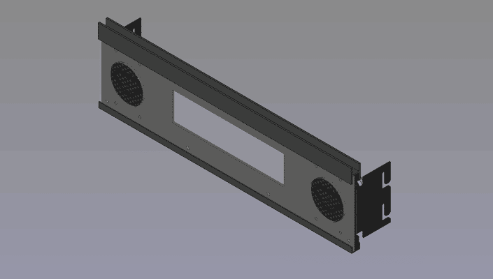
The finished CAD model of the speaker panel
One of the main challenges I faced was just trying to figure out how to make a hexagonal grill for the speakers with the TriOptimum logo overlaid. In OpenSCAD, I’d just use for-loops and the difference operation to “cut” the hexagons out of panel’s profile and the union operation to add back the logo but it’s not that simple in FreeCAD.
The problem I ran into is that FreeCAD’s sketch workbench doesn’t appear to have any way of creating a repeating pattern. Manually sketching each grill hole would take forever and bog down the program so I had to find another solution. Thankfully, someone else already made a tutorial for creating grills in FreeCAD. I had to deviate some to get the results I needed but ultimately, the process boiled-down to the following:
FreeCAD grill tutorial
Disclaimer
I’ve read it’s not good to mix the PartDesign and Part workbenches but this is the only way I knew how to do this and it hasn’t broken on me yet.- Create a master sketch of the speaker panel with all the mounting holes and DMD cutout but no speaker holes
- Create a master sketch of a single grill hole (a hexagon in my case)
- Create a master sketch of the TriOptimum logo I wanted over the grill
- Add dimensions to a master spreadsheet defining width and height of the hole grid as well as how many holes should be present horizontally and vertically
- Create a grill “punch” file which will serve as a virtual hole punch for making the grill
- Create a PartDesign body for the grill grid
- Add a backing-plate which all the hexagons will attach to (since a PartDesign body doesn’t allow disconnected geometry)
- Extrude a single hexagon from the plate near the corner
- Use the MultiTransform operation to first repeat that hexagon into a line across the plate and then again to repeat that line into a grid using the dimensions from the spreadsheet to define the length and occurrences of each pattern (all extrusions must touch the plate or the operation will fail)
- Create a second PartDesign body which will serve as a mask to remove parts of the grid where the logo will be
- Create a backing-plate (again just to ensure all parts of the logo will be connected)
- Extrude a cylinder from the backing-plate the diameter you want the speaker hole to be
- Pocket the logo from the cylinder such that areas you want the logo to show are not solid but do not allow the pocket to go all the way through the plate or the operation may fail if the logo has disconnected geometry
- Create a new Part body and move both PartDesign bodies into it
- Perform an intersection of the bodies so that you’re left with the “punch” for the grill
- Remove any shapes from the punch that would produce holes too small for your fabricator to cut by applying a CompoundFilter and setting the Window To value to a number high enough to remove the excessively small shapes
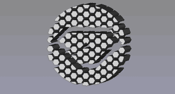
The "punch" for the speaker grills
- Create a PartDesign body for the grill grid
- Create a panel file for the final part
- Add a PartDesign body
- Extrude the speaker panel sketch to whatever thickness your material is
- Add a Part body and move the PartDesign body under it
- Link the punch file and move it to left speaker position; repeat for the right
- Apply a cut operation on the Part body using the left and right punch bodies
- Export the final Part body as a DXF to get the final cutting profile
Yeah… it’s a complicated mess that would have taken a fraction of the time to design in OpenSCAD but to be fair there are many other parts in this design that would be a nightmare to make in OpenSCAD.
Speakers
Given the size of the display, I only had room for ~2" (50mm) front speakers. That’s not a lot of room to work with but thankfully 2" speakers are a common standard so there’s plenty to choose from. I don’t know much (or anything) about audio but I do like how my Logitech X-140’s reproduce System Shock’s soundtrack so I looked for speakers that sounded similar.
As is a theme for my harebrained schemes, I found some really cheap speakers on Amazon and figured I’d give those a test first. I’ve heard it’s pretty common for a lot of higher priced speakers to actually be poor quality so I figured I’d start from the lowest possible price and work my way up instead of overpaying from the start.
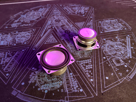
At only $4 each, these are surprisingly not terrible
And honestly… I didn’t think they sounded that bad… or at least not when I had them on my desk. They had absolutely no bass at first when I had them propped up on their boxes but sitting them on my desk greatly improved their sound. Thing is though, I know mounting them in the backbox would help but I don’t think it would have quite the same effect as sitting them on a wooden desk. I assumed I’d need speakers that had more bass on their own if I wanted them to sound good.
I should mention at this stage I was determined not to buy a dedicated subwoofer for a few reasons:
- I couldn’t find a subwoofer small enough to fit under the playfield (even 6" subs are quite tall)
- My cabinet isn’t meant to have legs so even if I could mount it in the bottom, it would be pressed against the table
- The cheap amp I bought to test with was only 2 channel
Anways, based on some reviews I decided to order two different speakers from Dayton Audio in the hopes that one would have better bass: the PC68-4 and the DMA58-4. Both models sounded very similar to me but I felt the DMA58-4 was slightly closer to what I wanted; however, neither solved the bass issue.
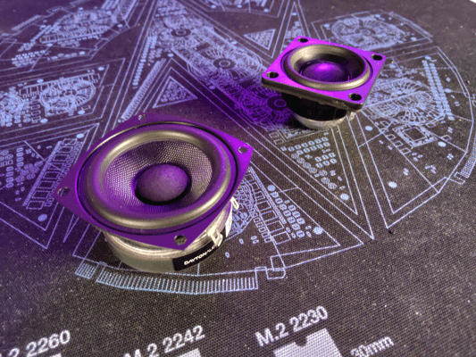
The PC68-4 (left) and the DMA58-4 (right)
It might be possible to get small speakers with good bass but I decided to go ahead and get the smallest subwoofer I could find along with a better amp. Unsurprisingly, this greatly improved the sound. Even the original cheap speakers sounded much better with the sub; however, I decided to stick with the DMA58-4s.
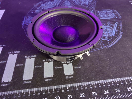
The sub may look small on camera but it's going to be a challenge to fit into such a small cabinet
Having good audio is great and all but it won’t do me any good if I can’t fit the speakers in the machine. Like I mentioned earlier, I can’t really put the sub in the bottom like a full size machine since it would interfere with mechs on the bottom of the playfield.
I don't have any mechs in the center of the playfield yet but if I did the speaker would interfere
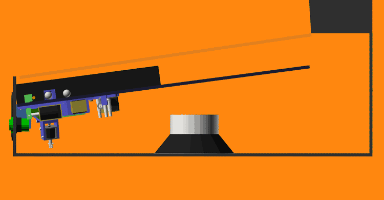
Mounting the sub in the back clears the playfield; although, I may regret this later when I need to install the power supplies. I’m hoping the sub will sound okay in the back.

The sub's magnet is pretty close to the back of the playfield so I may need to move it down some to not pull the ball
New test stand
The last test stand I designed worked but I had some issues with it:
- The playfield kept falling out when I moved the stand
- There wasn’t anywhere to mount the backbox electronics
- The front extrusions weren’t held on very well
- It wasn’t easy to adjust its width
- Overall it just felt flimsy
Using most of the same parts and some new brackets, I rebuilt the stand into something much more workable. The new stand is more rigid and adds hooks to the playfield so it can’t fall out anymore. The new design also gives me extra room at the back to mount electronics and room at the top for the DMD.
I'm confident this thing has more bolts in it than the average fighter jet
Intro animation
The fancy new speaker panel wouldn’t do me much good without something to display on it which is why I’ve been practicing my pixel art and working to reimagine the game’s intro cutscene as a DMD animation.
It’s still a work in progress but the idea is to have SHODAN’s into speech play while alternating between sequences like this and the high-scores.
Text-to-speech
If you’ve ever played the original System Shock then you’ll know SHODAN isn’t the only voice of Citadel station. There is a second artificial male voice used for things like countdowns and the reactivation of medical chambers. This second voice, commonly called the Citadel PA, is very clearly computer generated.
Why does this matter? Well while I do plan on using voice lines from SHODAN as callouts, the selection of lines is fairly limited and recording new lines in her iconic style would be difficult. That’s why I want to determine how the PA’s voice was made so I can recreate it for most pinball-specific lines.
To start, I listened to every interview I could find with the game’s composer, Greg LoPiccolo, for any clues on the voice’s design. Greg stated that he used SoundDesigner on a Mac to edit the audio and noted that it was very limited having no DSP effects and only being capable of cutting, pasting, EQ adjustments, and pitch shifting. Unfortunately, Greg never specifically mentions what speech synthesizer he used for the PA voice throughout any of the interviews I found ([1], [2], [3], [4], [5]) but this was a good start.
Given Greg had very limited editing capabilities at the time, I’m assuming he used the output of the speech synthesizer mostly as-is which should make it easier to narrow down. I started looking into which synthesizers were available before 1995 since the CD release of the game (the version with voice lines) released December 1994. So far, I’ve found the following:
- SAM - 1982
- DECtalk - 1984
- MacinTalk - 1984
- Dr. Sbaitso - 1991
- MacinTalk 2 - 1994
MacinTalk 3
MacinTalk 3 appears in many searches as being far more capable than its predecessors but what little information I can find seems to indicate it didn’t release until 1995. While it’s not unheard of for a game studio to have early hardware/software access to incentivize making games for a platform, I’m not convinced that would include something like an unreleased version of MacinTalk.I took an example line from the game and tried to reproduce it using emulators for each of the synthesizers. Below are the best examples I could come up with for now:
Based on this test, I’m fairly certain that DecTalk was the synthesizer used. The pronunciation, inflection, and speed match the original line far closer than others. That said, you may have noticed that I was being very specific about the version of DecTalk I tested and there’s good reason for that. I’ve found each version of DecTalk sounds very different; additionally, some of the settings that work in one build just sound like noise in others. Just listen to the default 4.61 and 4.62 samples back-to-back and you’ll hear a difference. Unfortunately, I can’t find any other versions of DecTalk to test with so 4.61 build 109 is the closest I have.
DecTalk has tons of settings and I haven’t really even begun trying to adjust the pitch or EQ of its samples so I still have a long way to go before I can replicate the PA voice. Despite the effort required, I’m confident I’ll get a better result from this approach than trying to train an AI text-to-speech model on what few PA lines there are; although, I have considered using machine learning to try and find the optimal combination of DecTalk, EQ, and pitch settings but for now that seems like it will take more effort than it’s worth.
Other updates
Pushing buttons
Something I forgot to mention in the last post were the flipper buttons I’m using. While these look like standard arcade buttons they’re much cooler. Pinball machines typically use leaf switches which have a smooth actuation while most arcade switches use clicky microswitches; unfortunately, the switches made for pinball typically have a large leaf switch attached to the back that takes up too much space and I don’t like clicky arcade switches.
The switches I’m using are special though. They look like arcade switches but they actually contain an integrated leaf switch. This makes them compact without compromising the switch feel. I got these at Ultimarc but they may be carried elsewhere.

Here you can see the terminals of the integrated leaf switch
I haven’t decided the final switch color for the machine so I bought a pair of every color offered.
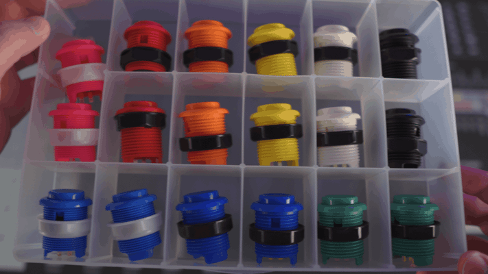
Some of these colors are giving me ideas for future machines
Polycarbonate
I mentioned back in my post about slingshots, that I intended to cover my playfield with a thin layer of polycarbonate to cover the holes for the inductive probes. Without the polycarbonate, the ball would skip over these holes so I needed to get some for playtesting.
Now unfortunately, I don’t have the tools (or the room for the tools) to make precision cuts in polycarbonate and I couldn’t find any company willing to machine it either. Companies like SendCutSend will machine thicker plates no problem but nobody appears to offer the thinner sheets I need. I figured my best bet for getting accurate cuts in the poly was to get a template made from a different material and use a plunge router to trace it into the poly. That said, I didn’t want to invest in a template at this stage so I decided to just order some precut poly from Amazon that happened to match the dimensions of the playfield and make the rest of the cuts by hand.
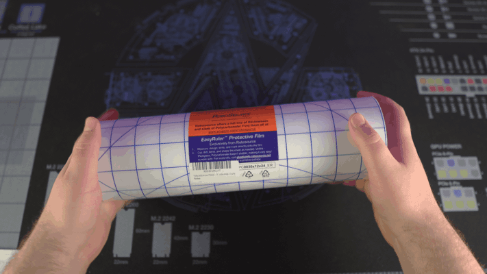
The 12"x24" roll of polycarbonate I found on Amazon
That was a mistake. The poly I got from Amazon shipped rolled and refused to lay flat even after being left under a weight for a week. I’ve never had to flatten poly before but the resources I initially found said the best approach is to sandwich it between two plates of glass and apply light heat for a short period. I had a feeling this wouldn’t end well but I was curious so I decided to order a couple cheap glass plates and a heated mat to test it out.
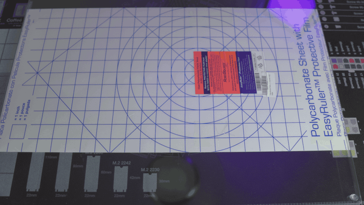
The polycarbonate between two glass plates
Why a heated mat? Well, I figured it would provide fairly even heating and be easier to keep at the target temperature. In a shock to no one, I cheaped out and the mat I got could only just barely reach 97F. I even tried insulating it from the air with a thick towel but the highest temperature I could get was 102F. With this low temperature, the poly was getting warm but it just wasn’t enough to do anything.
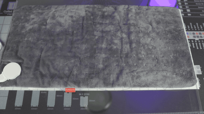
It's hard to describe just how sketchy this heating mat feels in person
At this point, I decided to go for broke and got out the hot air gun. Well, I actually tried using a hair dryer at first but it was too smart for its own good and refused to heat up the polycarbonate at close range. My sketchy hot air gun had no such issues though.

You can see just how warped the poly was with the top sheet of glass off
Despite my hot air gun being able to melt low temp solder, it still couldn’t heat the poly enough to relax it. I could get sections to lay somewhat flat if I applied heat for several seconds in one spot but it wouldn’t stay down even if I quickly pressed it between the glass and allowed it to cool under pressure.
I’m really not sure why this didn’t work. Honestly, I was surprised applying direct heat with the hot air gun didn’t outright melt the plastic (I was nearly touching the tip of the gun to the plastic most of the time). All I can think is maybe the plastic and the glass were just too much for the little gun to saturate.
At any rate, I decided to move on and just order poly from a different supplier. The new sheets came from TAP Plastics and while they did arrive rolled, they did lay mostly flat after leaving them sandwiched between the glass for a few days. Turns out buying supplies from reputable places saves time. Imagine that.
All that said, I don’t think I’m going to use the poly after all. In the FAST Pinball Slack group, some people brought up how polycarbonate sheets will actually expand with heat from the machine and cause the surface to warp. I’m also still not confident in my ability to cut the precise holes I need plus I may have found a better solution to my slingshots.
“Micro” switches
I was randomly searching Amazon, as you do, and came across something I’ve never seen before. Extremely tiny leaf switches.

5/8" pinball for scale
Size isn’t everything though. What really matters is actuation force as the mini pinballs don’t even weigh enough to actuate a keyboard switch. And…
They’re perfect!
These little switches are easily actuated by the weight of the ball and even seem to resist vibration. I have no idea what these switches were designed for but I found even more variants of them on AliExpress and eBay with different mounting hole orientations. With these new switches, I’m re-evaluating the design of the slingshots and rollovers to use these instead. If I can get rid of the inductive probes, that would completely negate the need for a polycarbonate layer over the playfield.
Flipper redesign
Speaking of redesigns, one of the main reasons I switched to FreeCAD was to make designing the new flipper mech easier and I cannot stress just how much it’s helped. I haven’t quite landed on a final design just yet but I do have a couple interesting prototypes.
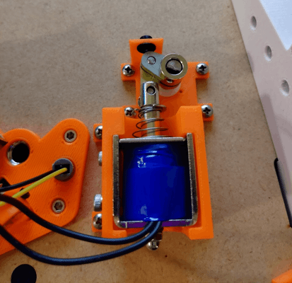
The first of the prototypes printed and installed
There’re a few big changes with this new design. For starters, the entire linkage is metal with stainless steel crank arms and a brass link. Less obvious is the custom machined rotary shaft with flats to drive to the flipper and crank arm. I’ve also switched to a much smaller solenoid and added a rubber backstop.
That’s sort of where the good things end with this design though. I chose to use a flat to connect the crank arm and shaft despite knowing that full-sized machines just clamped onto a round shaft to allow for adjustment. Suffice to say, I needed that adjustment. I’ve found that even slight variations in placement and spring tension result in the flipper bat being misaligned with the return lane. In this prototype, there is no way to adjust the resting position of the bat aside from cutting a new crank arm.
Furthermore, I want to switch the design over to tension springs. It’s my understanding that compression springs wear out faster and provide less consistent force compared to a tension spring. Tension springs are also less likely to bind up.
Finally, I need to add an end-of-stroke switch to the mech so the software knows when the flipper bat is fully rotated. This is critical because the solenoid will overheat if given full power for too long. To allow players to hold flippers up, the coil needs to switch to low power once the bat has reached the end of it’s stroke. While you can use a timer to guess how long the bat should be given full power, that won’t account for if the bat starts to drop from a direct impact and would be a pain to tune.
As for the second prototype, I’ve been wanting to raise the flipper mech off the bottom of the playfield so I could use the space under it for a secret feature I’m working on. To do this, I designed a custom metal mounting bracket based on its larger counterpart.
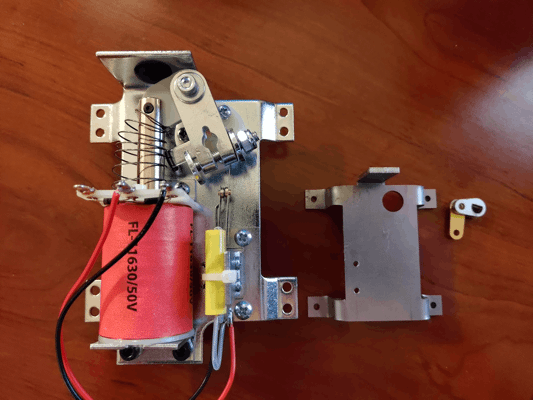
Left is an off-the-shelf flipper bracket, right is my mini bracket
It’s not perfect (in fact I can’t even mount the mechanics to it because I screwed up hole placements) but raising the flipper mechanics off the wood will allow me to place the fasteners I need under the mech.
Going FAST
For my earlier tests, I was just using an Arduino with a relay shield to control my solenoids. That worked for simpler mechs but my flippers require PWM so I needed a better solution. Around that time, FAST Pinball’s boards were back in stock so I picked up a Neuron, smart power filter board, I/O board, and some opto boards. These should give me just enough I/O to run my playfield’s lower-third. Even better, this means I can finally start using Mission Pinball Framework for my game rules instead of writing temporary C++ programs.
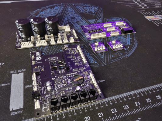
Hopefully all these boards will fit into the final cabinet without too much trouble
Burn it all down
With all this progress, you might be surprised to hear that I need to redo most of it.
Up till now, I’ve been using 6mm MDF for the playfield. I knew MDF wouldn’t work as a long-term solution so my plan was to eventually switch to 6mm Baltic birch plywood for the final playfield; however, I’ve been rethinking that decision for some time. I just don’t think that 6mm birch will be enough to withstand the weight of all the mechs or offer enough material for the screws to hold onto.
After putting it all together, I’ve made the painful decision to redesign the machine to use 1/2" Baltic birch plywood instead… which means the flipper, auto-plunger, ball trough, ball ejector, and slingshot all need to be redesigned. It’s painful but I think having more material to mount mechs into will pay off in the long run.
Building a Test Stand | Half Scale Pinball
On my way to a playable machine
These past months, I’ve been working to get the lower-third of the machine in a playable state so I can finally playtest. Thankfully, I’m nearly done as all I have left is the redesign of the flipper mech. The only problem is I didn’t have a way of propping the playfield at the correct angle or holding its sidewalls in place.
With full size machines, the playfield dimensions are at least somewhat standardized so you can borrow a cabinet from another machine or build your own from plans online but I’m not making a standard playfield. I do intend to build a cabinet for my machine but my playfield dimensions could still change so I don’t want to waste the time or money on the cabinet. Instead, I wanted to build something adjustable.
Aluminum extrusion FTW
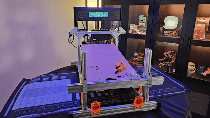
I figured my best option was to build the test stand from aluminum extrusion. It’s relatively cheap, available precut, and reusable. I spent a few days in CAD and came up with this design.
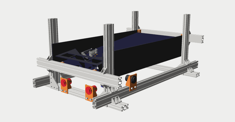
This isn't how you'd normally join extrusions but doing it this way lets each side slide in/out to fit the playfield
Now, extrusion isn’t a precision component. The beams can be warped and bowed (they are after all the product of forcing molten aluminum through a die). Thing is, even if the extrusions were perfect, there’s no guarantee my table or floor are. To compensate for that, the playfield is resting on four adjustable carriages for levelling.
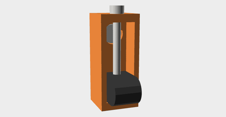
Each playfield support consists of an M3 bolt as a lead screw and a carriage with heatset insert that engages with it
Assembly
One hour and 96 bolts later and I have the stand assembled
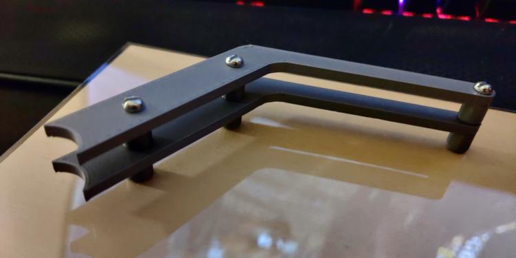
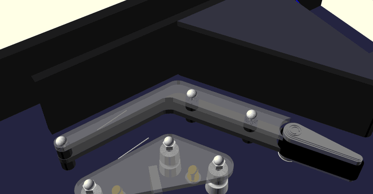
Assembly went smoothly for the most part but there was one unforeseen problem. For the extrusions supporting the playfield, there are plenty of plates and brackets designed to join extrusions whose channels are parallel but I couldn’t find anything meant to join extrusions with perpendicular channels. What do I mean? Well take a look at these renders.
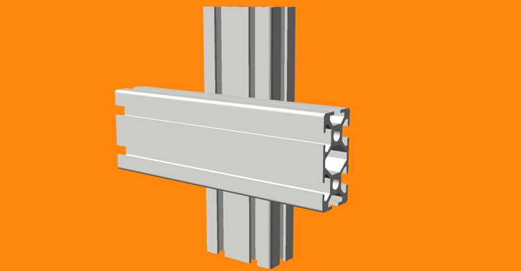
This is how I want to join my extrusions
Now, you wouldn’t normally join extrusions like this; however, joining them the normal way would require cutting them to exact sizes and defeat the purpose of the stand. Joining them this way allows for excess extrusion so I can slide the joints closer/further apart to accomidate the playfield.
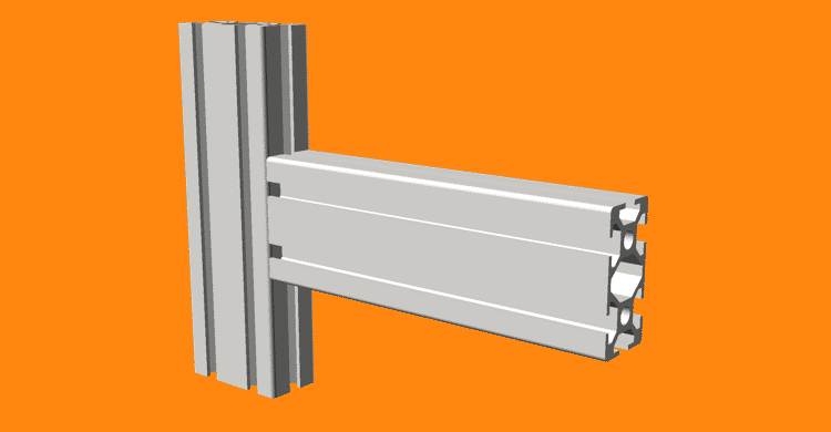
But this is how extrusions are intended to be joined
But wait, what about those little corner brackets in the picture? Well, there in lies the problem. You see, those brackets actually have little tabs on bottom meant to align them with the channel. Unfortunately, those tabs are spaced too far apart to fit in the channel sideways so for one of the perpendicular extrusions it’s not actually making contact with the flat part of the bracket.
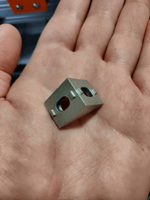
Note how the tabs are thin enough to fit in the channel one way but are too far apart to fit the other way
While this does affect how precise the joint angles are, that isn’t really the biggest problem here. What I soon discovered was these tabs dig into the sides of the extrusion and effectively lock it in place even when you loosen the bolts. This makes it much more fiddly to adjust the dimensions of the stand than I had intended.
I’ve since thought of a few other ways I could have constructed the stand to avoid this but it’s good enough for now that I’m fine with it as is. Also note, I did find some different brackets that don’t have the alignment tabs; although, they may not work for this application since they are designed to attach from the ends not the channels.
If you get nothing else from this post, just take this as a word of caution in case you plan on building something out of aluminum extrusion as well. Hackaday has a great article on how to properly join and constrain extrusions if you’re interested.
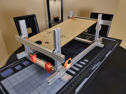
Playfield
You may have already noticed the fancy new lasercut playfield. It’s a bit barren and this is far from a final layout (I don’t even know yet if I’ll be using the standard “Italian” design) but it will at least let me mount all the mechs I’ve designed for testing.
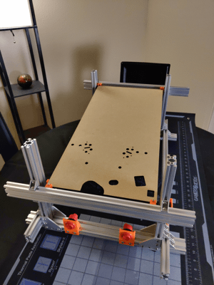
The lasercut playfield fits nicely in the new stand
A fiberoptic DMD?! | Half Scale Pinball
…but why
You, being a sane and reasonable individual, are probably wondering how I could possibly think it was a good idea to build a fiberoptic panel for my pinball machine’s DMD. Frankly, I don’t even have a great answer to that so I’m going to mix things up this post and just present this whole ordeal in the order of events that led me here. I realize I went pretty far off the rails with this one so bear with me.
Design requirements
This all started when I got thinking what kind of display I wanted for the machine. While pinball has used many display types over the years, I wanted a display capable of showing bitmap animations which left me with two options: a dot-matrix display (DMD) or an OLED/LCD screen.
System Shock is fairly low resolution by modern standards so I felt the look of larger pixels would suit it better and while I knew it was possible to emulate the look of a DMD on a screen, I still preferred the look of a real DMD’s rounded pixels. So problem solved, right? Just buy a small DMD and… this is where things started to get messy.
Most pinball DMDs have an aspect ratio of 4:1 with a resolution of 128x32 pixels. Modern DMDs are typically constructed from two 64x32 pixel modules commonly used for digital signage. Unfortunately, these off-the-shelf modules are not, to my knowledge, available in pitches less than 2mm (pitch being the center-to-center distance of each pixel). That may seem small on paper but consider that a 128x32 display with a 2mm pitch would still be 256mmx64mm (~10"x2.5"). Again, that may seem small but my entire backbox is only 14" wide and I still have to fit speakers on either side of the display. Not to mention a full size display is just 320mmx80mm (~12.6x3.1") so it’s not even that much smaller. Clearly, I needed to find a better solution.
A full size display technically fits but something tells me the game wouldn't sound quite right without its front speakers!
Half resolution panel
The “obvious” next question was: since everything else on the machine is half-scale, why not halve the DMD resolution as well? On paper, this solved a lot of problems since a display with exactly half the resolution would fit perfectly in a half-scale backbox; however, as is often the case, ideas that sound good on paper don’t always work so well in practice.
The fundamental problem with this approach is that a pinball’s DMD already has a soul-crushingly small resolution of just 128x32. Aurich on Pinside already did a great job explaining why this resolution is so limiting so I won’t rant about it here but just looking at the image below should make it clear just how little information you can fit in this resolution with any semblance of theming.
Even on a full resolution DMD, the TriOptimum logo from System Shock barely fits
Now halve that already small display to just 64x16 (a resolution barely larger than some Tamagotchi models) and you’re left with something unusable for the kinds of animations I want (more on those later).

The font used throughout System Shock's levels is barely recognizable at a 64x16 resolution
Custom panels
If I had to pick a moment where things really started to spiral out of control, it would be here. Hellbent on not using a screen, this is where I checked my sanity at the door and started down the path of building a custom DMD.
8x8 matrices
The first idea that came to mind was to buy a bunch of 8x8 pixel matrices and arrange them into a custom display. The problems with this approach became apparent right away though as I couldn’t find anybody selling these matrices in a size anywhere near small enough. Just using the bog-standard size, I would only be able to achieve a resolution of 32x8.
The black outline represents the size of a half-scale DMD. Unfortunately, these 8x8 matrices are so big that only four fit in the space.
Through-hole matrix
Since prebuilt panels were too big, I figured I could just wire up a panel from scratch using through-hole LEDs. I had seen a video a while back from Ben Heck about the custom DMD he built for his Bill Paxton machine which gave me confidence this would work; however, I soon learned the smallest through-hole LEDs I could get (1.8mm) were still too big. Upon re-watching Ben’s video, I also realized his matrix wasn’t the full resolution so I lost confidence that I’d even be able to wire a full resolution display manually.
Surface-mount matrix
Since through-hole LEDs were too big, I turned my attention to SMD LEDs. There are a few different sizes of SMD LEDs but the smallest I could find were so called “NanoPoint LEDs” at a size of just 0.65mmx0.35mm. But wait, didn’t I just say I couldn’t manually solder the 4096 LEDs my panel would require? Yes; however, my plan was to have the LEDs pre-installed on a custom PCB through a service like PCBWay. That is at least until I totaled up the cost. The LEDs alone would be over $500 plus another $300-400 for automated assembly. I’m not opposed to shelling out money for this project but nearly $1k for a display is just wasteful!
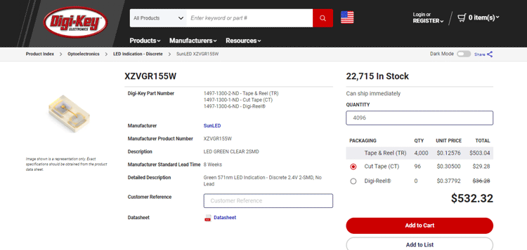
The cost of 128x32 (4096) NanoPoint LEDs from DigiKey
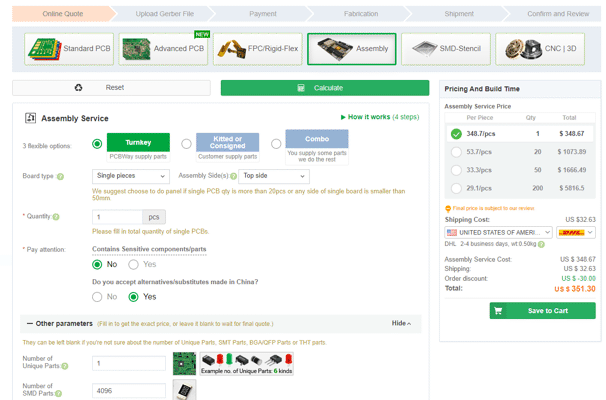
The cost to have PCBWay assemble a board with 4096 SMD components
Cost wasn’t even the main issue with this approach. Regardless of LED size, there are still physical limits on how close I can pack them on a PCB and still be able to route their power and ground traces. There may have been a way to make it work but I don’t have the PCB design experience (or any for that matter) to pull it off.
Fiberoptics
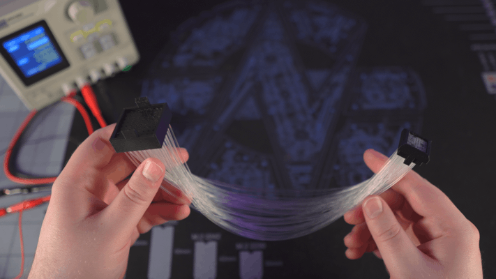
Of all the issues I mentioned above, one problem was common to them all: the physical limitation of how closely LEDs can be packed together. This got me thinking… if I can’t fit the LEDs any tighter, could I instead route the light from a larger panel to a smaller display? I briefly considered using lenses but that idea was soon squashed by another: fiberoptics.
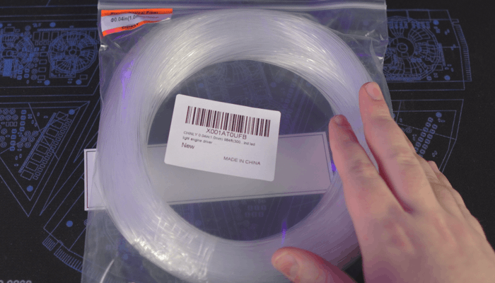
Bundles of fiberoptic filament like this are readily available on Amazon in many different lengths and diameters
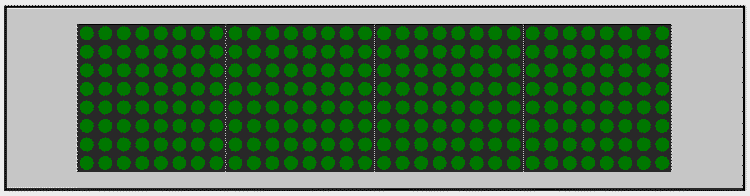
I did some quick searching to see if anyone else had attempted something similar and sure enough two others had already uploaded videos of their designs: elliotmade and Dr. Tõnis Gadgets. With that validation, this seemed like a good idea; however, I couldn’t decide on how to build the display. My two thoughts were to either use a larger diameter filament and simply pack the filaments together for larger pixels or to use a smaller diameter filament and build a grid to space the dots out (like what the YouTubers had done). For testing, I decided to use one of the 8x8 matrices I bought earlier to prototype each approach.
Packed filaments
My plan for the “packed filament” approach was to build a square frame which would hold the filaments tightly together. I hoped the filaments would naturally arrange themselves into an 8x8 grid if there was no free space to go anywhere else. I was concerned some filaments, particularly in the middle of the matrix, would end up closer or further back and thus darker than others so I also built a bezel which would hold a thin piece of polycarbonate to the frame acting both as a display surface and a hard stop to push the filaments to. For this test, I chose to use 1.5mm filament as this was the largest I could go without a 128x32 display becoming too big.
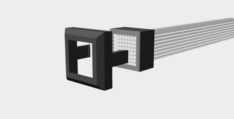
Exploded view of the assembly
On the LED side, I simply created a part which would snap onto the 8x8 matrix and allow the fibers to be press-fit into holes over each LED. I wanted to ensure the light from one LED couldn’t travel to a different fiber so I designed the part to fit flush against the panel but recess the fibers back to minimize light polution.
Note how the filaments don't go all the way through the mount. My thought being this would help prevent light bleed.
Unfortunately, the problems with this design were severe enough I couldn’t even test it. Right away, I found the filament did not fit into the frame I designed. I thought at first the filament was either larger than advertised or my printer undersized the part; however, neither of these were the problem. The issue turned out to be the filament, which hard been shipped as a roll, was trying to remain curved and thus taking up more space. I found I could just barely fit the filaments into the frame if I applied enough force but in doing so the filaments were not aligning into a grid like I had hoped and were instead forcing the frame apart leaving gaps in the display.

Despite my best efforts, I couldn't get the filaments to align into a grid
I probably could fix this with enough time and patience but seeing as how I was already encountering issues in an 8x8 display, I felt it best not to attempt with a larger panel.
Spaced filaments
For my second test, I borrowed most of the design from the previous experiment but changed the frame to be a solid piece with a grid of holes. I used 1mm filament for this test and initially designed the part with a hole pitch of 1.5mm to result in the same size display as the previous experiment.
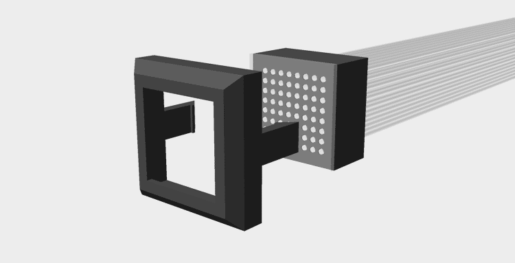
Exploded view of the assembly
This didn’t work out as planned either though. My printer has a 0.4mm nozzle and despite my best efforts there just wasn’t any way I could slice the part and have it come out correctly at this resolution.
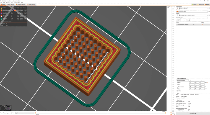
With some tinkering, it was possible to get the slicer to accurately slice the thin walls; however, my printer just couldn't handle it
In desperation, I tried increasing the hole pitch to 1.9mm and reducing the final resolution to only 100x25 dots to maintain a similar size. Thankfully, this did slice without error but my problems weren’t over yet. The holes in the frame came out inconsistent. Some were too large and others too small. Rather than spend an eternity tweaking the hole sizes and slicer settings, I felt it would be best to just drill out all the holes to 1.5mm and glue the filaments in place.
This was a mistake.
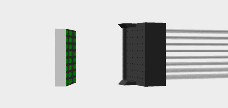
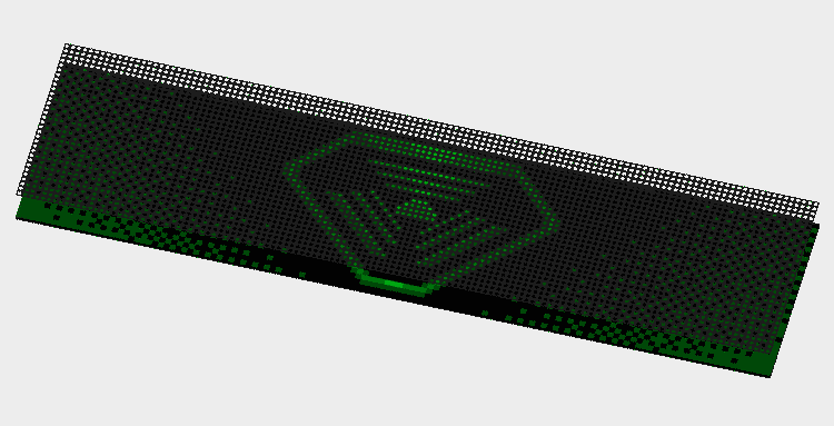
It took me four days of gluing to finally complete the display. Not only did I have to wait a couple hours between each row to allow the glue to dry (accelerant couldn’t reach the glue inside the holes) but it took ages to find which filament needed to go where. I knew I didn’t technically need to line the filaments up on the DMD and display sides since any mismatch could be corrected in software but I’m not a fan of fixing hardware problems in software.
While the display face may look messy from the glue, I suspect some window tint could hide the marks without significantly affecting the lights
The final assembly was done and to my delight it actually worked quite well save for two problems. The first being some filaments pulled out slightly from the frame while drying resulting in a few pixels which are noticeably darker than others. This could probably have been fixed with more QC but the second problem was more fundamental.
While obvious, the dark pixel isn't the only problem here. Look closely and you'll notice there is a fair bit of light bleed to adjacent pixels.
I had completely overlooked that a bundle of the filament would no longer be flexible so the two ends of the display could not be moved. What’s more, the curve of the filaments forced the assembly to contort into a curve as well making it much harder to work with. Like most issues I described, there is almost certainly a way to get around this in the final machine but at this point I was exhausted, defeated, and was frankly bored of this who endeavor.
Compromise
While none of the approaches I tested worked, I don’t feel the time was wasted. I learned a fair bit along the way and I’m sure I can find some other uses for the fiberoptics in the future. That said, I still need a display.
I decided to finally do the reasonable thing and resolve to just use an OLED panel but I still wasn’t happy with how how emulated DMDs look. I got to thinking though… what if I had the display render square pixels and just put a mask over the screen to make them round.
The pixels look a bit off here since the mask is raised above the surface of the screen
Frankly, I’m embarrassed I didn’t think of this sooner. It seems so obvious in hindsight. I thought at first the mask layer might be hard to manufacture given the hole size and spacing but I got an online quote to machine it from metal for around $350. That’s certainly not cheap but it’s not completely unreasonable either. I do have a couple other ideas though. I figure I could try with vinyl; although, I worry it will be difficult to apply without distorting. I’m also curious if a blank PCB would work given PCB routing is typically very precise and quite cheap.
256x64 panel
That just leaves one last problem, the OLED panel.
I’m usually skeptical of panels advertised for use with Arduino and Raspberry PI boards as they’re often controlled via slow interfaces that limit the refresh rate; however, I did find a 256x64px OLED panel with options for a parallel interface and even natively supports 16 levels of greyscale per-pixel (though I only plan to use 4).
Like the other pre-made displays I mentioned earlier in this post, the only problem with this model is it’s size… except in this case it’s a bit too small. The pixels of this display are only 0.53mm so the entire display is just ~135x34mm (~5.3"x1.3"). That’s a fair bit smaller than the 160mmx40mm (~6.3"x1.6") of a true half-scale display and the 192mmx48mm (~7.5"x1.9") size I was aiming for with the fiberoptic panels. Even with the speakers on either side, I think this panel would look a bit too small; although, I may get one to try out anyways.
What do you think of the square speaker grills? They're still a work in progress but I'm worried they make it look like the front-end of a jeep.
High resolution panel
Another option would be to just buy a replacement panel for a phone, tablet, or similar and find a controller to drive it. I believe this would be the cheapest option by far given mobile displays are a commodity; however, finding one wide enough to fill out the space without being too tall will be a challenge. There is also no guarantee that I’ll be able to find a display driver capable of running it.
With some searching, I eventually found another promising option. 8.8" (~223mm) 1920x480 displays are apparently common in automotive applications and you can even buy some that natively accept HDMI. Size is once again a problem here though as the 217mmx54mm (8.5"x2.1") area is a bit bigger than I’d like. I could hide the extra pixels behind the bezel but it encroaches on the speakers at that point.
With this X-ray, you can see just how much of the screen would be cropped and why the speakers have to be moved to accommodate it
Animation sneak peek
Ultimately, I’m going to put more display testing aside for a bit and focus on other parts of the machine. That said, I want to leave you with some ideas I’ve been working on for potential DMD animations.
Disclaimer: None of these images are final. I don’t claim to be great with pixel art so I may even commission someone to remake them later.
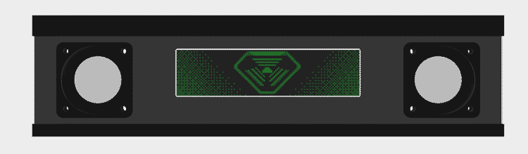
TriOptimum Logo
The TriOptimum logo I’ve shown throughout this post is meant to be part of the attract mode. My intent is to periodically play a DMD-rendition of System Shock’s opening video. The green text of the hacker’s laptop is a big part of the reason I want a green DMD.
The gradients are just here to fill in space in the screenshot. They won't be there in the final animation.
Fonts
System Shock makes use of several different fonts; however, my favorite is the retro-futuristic font, StopD, used to label each floor of the station. I plan on using this font for any large text in the game. Interestingly, System Shock uses a customized variant of the font (or perhaps an older version) as some letters differ slightly (for example, the Y). For this reason, I’ve gone through screenshots of the game painstakingly re-creating their version of the font pixel-by-pixel.

I couldn't find an example of a W in System Shock's levels so this one is based on the original StopD font. More tweaking is needed to make it match the style of the others.
SHODAN
One of the creepiest occurrences in the original System Shock is how SHODAN’s face will periodically fade into view on displays showing static. I’ve always loved that detail and thought it would be cool if I could do something similar on the DMD. I think the effect works best when the player just barely catches it so my plan is to have the face rarely fade in behind the player’s score but dissappear before they have a chance to get a good look at it.

In game, SHODAN appears to have a wide smile on the in-game displays; however, I'm fairly certain this is just a side-effect of down-sampling her usual stoic expression to the lower resolution displays. Either way, I like how creepy her smile looks and decided to mimic it for my game.
CAD Files
By the way, I’ve published STLs to Printables and the CAD to GitHub if you really want to try making one of these fiberoptic displays as well; although, I really can’t recommend it for anything more than an experiment.
Ball Trough | Half Scale Pinball
It’s working! (finally)
I know it’s been a while since my last post but I have a good reason… Borderlands 2 is a lot longer than I remembered. No but seriously I’ve actually made a lot good progress since my last post and now have a working ball trough, ejector, and auto-plunger to show for it.
My hope was to complete prototypes of the ball trough, slingshots, flippers, auto-plunger, and lanes so that my next post could feature them all working together. Obviously, that didn’t happen. I kept running into problems here and there that pushed a full test out. A few of the problems still aren’t fully resolved but I felt it was best to show what I have now before waiting for everything to be final.
So what problems remain? I’m sure you didn’t ask but I’m going to tell you anyways:
- The current flipper design is bulky and likely to fall apart after moderate use
- The auto-plunger needs to operate at 24v which means I need to redesign the flippers to work at that voltage as well
- I designed for lane walls that were only 1/8" thick and I’m realizing now they’re too thin to screw into from the edge for mounting
I’ll talk more about those issues toward the end but for now let’s think positive and talk about that fancy new ball trough.
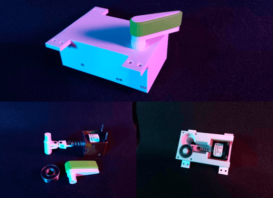
Design process
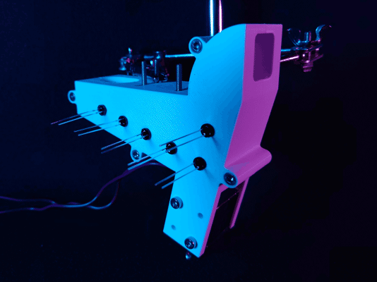
The ball trough assembly in all its vaporwavey goodness
This is actually the third iteration of the ball trough design. The original plan was to model the ball trough and ejector as one piece but make the ejector chute/scoop a separate component. I eventually realized there was no reason the two components couldn’t be combined for easier assembly.
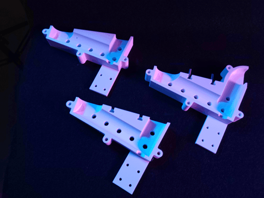
The progression of trough designs from first (left), second (bottom), to current (right)
I also revised the playfield mounts in the second and third revisions. The first revision had heat-set inserts pressed into the top with the intent being to bolt into them through the playfield. While this would have worked at first, I was concerned the heat-sets would work their way out over time. This wouldn’t have been a concern if I had pressed the heat-sets in from the bottom of the part but there was no easy way to do that without compromising functionality. An easier fix was to just switch which side had the nut and which had the bolt. The new design features T-slots allowing four M3 hex bolts to be held captive in the assembly. The threads of these bolts pass through the playfield from the bottom and the whole assembly is secured from the other side using washers and lock nuts.
That’s not to say heat-sets have no place in this design though. The final revision added heat-sets to one half of the assembly and counterbores to the other allowing the two halves to be bolted together more securely and without protrusions on either side. This was done to give me more clearance for the circuit boards later (more on that in a bit). During final assembly I intend to use thread locker on the heat-sets to ensure the bolts can’t back out from vibration (being careful of course to not get any on the plastic).
Updated solenoid
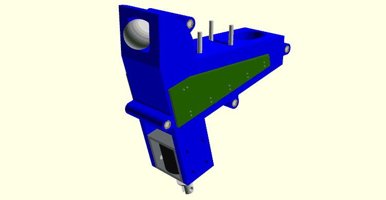
You don't want to know how long it took to render this image thanks to all the hacky Boolean operations I used to model it
Something that may not be obvious from the pictures is I’m no longer using the McMaster-Carr 70155K121 solenoid I tested back in February. While the 70155K121 was strong and much smaller than the first solenoid I tested, I managed to overlook one critical detail. The plunger on that solenoid was so long that it would have stuck out the bottom of the machine by half an inch.
Let this be a lesson to check dimensions in CAD before committing to a design 🤦♂️
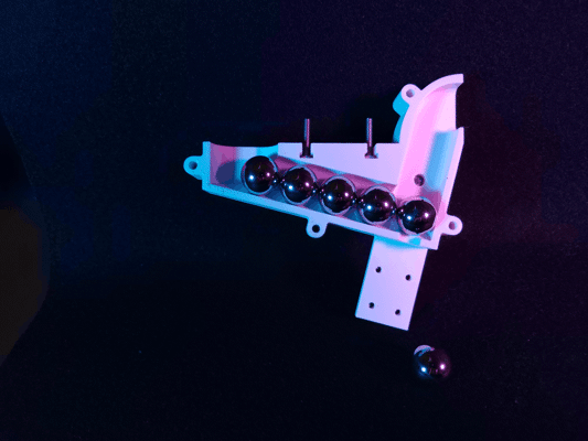
Silly mistakes aside, the ball ejector is now using the much cheaper T Tulead ADD06190484. I don’t know why I never thought to check Amazon for solenoids before but this model is cheaper, stronger, and smaller than any solenoid I previously tested. At only 12v, this model is perfectly capable of ejecting balls from the trough even when all 5 balls are loaded or when two become jammed in the ejector chute.
Speaking of jams…
Behind each ball is a hole for an infrared LED. The opposing side of the assembly has matching holes for photodiodes.
Just like it’s larger counterparts, my design uses five pairs of infrared LEDs and photoelectric diodes to detect how many balls are currently in the trough. The LED and diode pairs form an invisible beam at each ball position that is broken when a ball sits between them. The software simply needs to count how many photodiodes are blocked to determine how many balls are in reserve.
If a ball ever fails to eject or otherwise falls back into the chute, there is a good chance that it will become stacked on the next ball in the trough. An additional LED/diode pair is placed in the ejector chute to detect this condition. When this photodiode is blocked for more than a few hundred milliseconds, the software knows a malfunction has occurred and can either attempt to unjam itself or enter maintenance mode.
For the moment, I’m just hooking up jumper wires to the sensor pairs for testing. I would have liked to use proto-board; however, the LEDs are spaced 5/8" apart (the ball diameter) so the spacing doesn’t quite line up for standard pitch PCBs. Once the machine is nearing completion, I’ll send off for custom PCBs; additionally, I’ll add holes to the model for M2 heat-sets to mount the boards to.
WIP Auto-plunger
I'm not planning on adding a manual plunger to the System Shock pinball machine but I've designed the kicker arm to allow for one in future projects.
I created a rough working prototype of the auto-plunger but there is one big issue with the design. The kicker arm is only attached to the solenoid plunger using an M2 nut and bolt. While I could make the nut captive, the bolt will likely still become loose over time. I’d like to use a clevis pin instead; however, the smallest clevis pin I can find is 3mm in diameter but the hole in the plunger is closer to 2.8mm. I could try widening the hole but I’d rather just find a new solenoid model that’s more compatible and potentially smaller.
One thing I like about this design and have started incorporating into other mechs is how the solenoid is mounted. Screwing into the solenoid through the bracket does make replacing the solenoid more difficult but it makes for a much more stable mount. As an additional bonus, having the bolts held captive between the playfield and bracket ensures they can never work themselves loose even without thread locker.
If you’re familiar with how auto-plungers are designed for full-size machines you may have noticed there is no room for a kicker ball sensor with the solenoid mounted directly under the playfield. I didn’t have room on the right side of the shooter lane for an optical sensor either and I’d like to avoid capacitive sensors as I don’t like the look of sensor plates or conductive tape. I also considered making the kicker arm out of two insulated conductive plates and using the ball to complete a circuit between them but I decided to avoid custom metal parts for the moment. Ultimately, I’ve chosen to just use an inductive probe. Beneath the apron is a LJ8A3-2-Z/BY probe that pokes through the left shooter lane. With correct placement, I’ve found this probe to be very reliable at detecting when the ball settles on the kicker arm.
Revisiting the flipper
It's not easy to spot in the first picture but the flipper shaft passes through a precision flanged PTFE bushing just like it would on a full-sized machine
I’ve had a working flipper design since before I started this blog; however, experience designing other mechs and changes to the machine as a whole have made me rethink this design. For starters, the current design is unnecessarily bulky. This is largely due to the body being interchangeable between the right and left flipper assemblies; however, part of the bulk is due to the solenoid being mounted sideways and could be trimmed down by using the same mounting technique as the auto-plunger.
Parts availability and tooling is also somewhat of an issue. It’s not pictured above but the flipper bat and crank are reinforced by a 4mmx4mmx50mm shaft made of steel bar stock. The only 4mm bar stock I could find was made of hardened tool steel and wasn’t available in the length I needed. I was able to cut one shaft down to size with great difficulty but that’s not an endeavor I ever want to repeat. I’m currently investigating the options Misumi has for ordering custom rotary shafts as they look to have all the features I need (albeit at an eyewatering price).
Similar to my concern with the auto-plunger, I’m not happy with the linkage being attached using M2 nuts and bolts. Unlike the auto-plunger, the nut and bolt head are held captive; however, they do still become loose after a few shots. Switching to clevis pins should solve this issue but requires that I use a solenoid with a wide-enough hole to accommodate the pins I have in addition to making the linkage parts wider.
I also want to remove the skate bearing for simplicity sake. The bearing serves two purposes in the current design 1) to stabilize the crank shaft and 2) to prevent the crank body from sliding off the steel bar running through it. I don’t think I actually need the bearing to stabilize the shaft given it is already constrained by a fairly long precision PTFE bushing in the playfield; furthermore, the crank sliding off shouldn’t be a problem if I add a set screw.
This design isn’t all bad though. I was initially very worried that I wouldn’t be able to find flipper rubber in the right size or with many color options. As luck would have it, “Grifiti Band Joe” silicone bands ended up being the perfect size and came in several different colors. Newer prints of the flipper also include a rubber backstop to prevent damage to the linkage when the flipper resets.
Next steps
Once the flipper redesign is complete I’ll send off for a laser-cut playfield for an integration test. I also need to replace the relays in my prototype with MOSFETs so I can PWM the coils.
Just to level-set, all that’s a bit of a ways off though as I’m working on some upgrades to my 3D printer to support ABS printing and those upgrades will have it out of commission for a time. I also want the first full integration test to be well recorded so I’ll be spending longer than usual on its video.
Ball Ejector Testing | Half Scale Pinball
Ball trough design
On most pinball machines, a mechanism called the ball trough stores the balls not currently in play. Balls enter the trough through the playfield drain and are returned to play via a mechanism that ejects them back up to the shooter lane. There are several different styles of ball trough but I’ve decided to use the more modern design that requires only a single solenoid (pictured below).
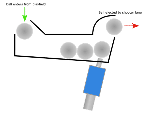
Side-view sketch of how a modern ball trough works. Not pictured are the physical or optical sensors used to detect how many balls are currently stored or if the ejector has jammed.
I like this design for two reasons: it’s dead simple and leaves more space above the playfield under the apron which I plan on using for a special feature I’ll talk about more in a future post. The main drawback to this approach is it takes considerably more space under the playfield due to the solenoid placement and the fact that most push solenoids have plungers that extend fairly far out the back.
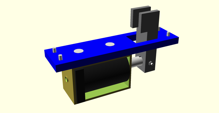
Solenoid testing
Given the limited space inside my pinball machine, I wanted to see just how big of a solenoid was required to eject the ball. To test the solenoids, I built a scoop roughly as tall as that needed in the final design and brackets to attach each solenoid to it. I ran each solenoid at an increasingly higher voltage starting at 12v until it was capable of ejecting a 5/8" (~15.87mm) ball with reasonable force.
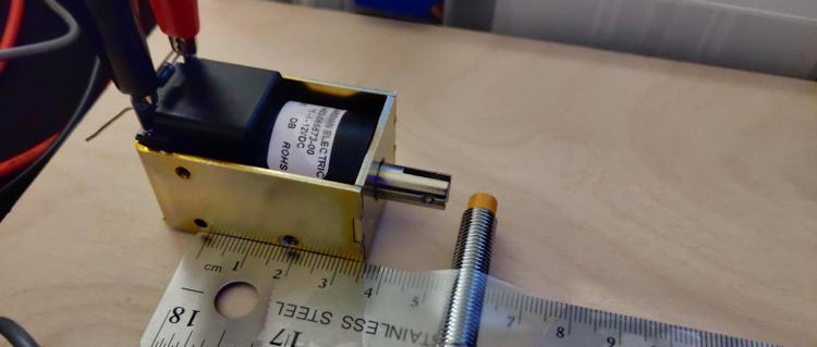
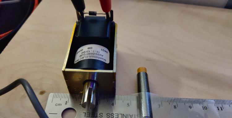
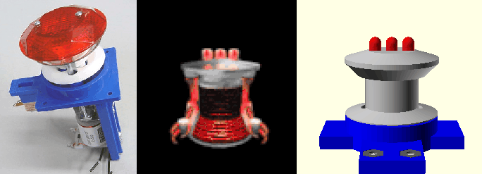
Guardian Electric A422-064104-04
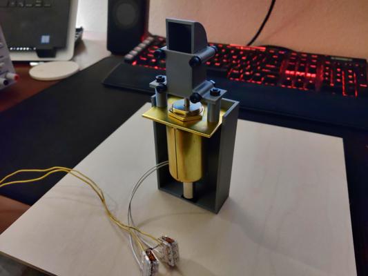
Testing the A422-064104-04 solenoid
The first solenoid I tested was the Guardian Electric A422-064104-04. This thing is a chungus but I picked it because I thought I would need at least a 1" (25mm) stroke length to get the ball up the chute (spoilers: I didn’t). I should also note that up to this point, I had been buying all my solenoids exclusively from Allied Electronics & Automation because they seemed to carry more models than other suppliers. In hindsight, this was a mistake as their stock mostly caters to industrial applications not as constrained by size.
While the solenoid did work, I had to run it at 18v to eject the ball with reasonable force and its size wasn’t even the worst of its problems. It’s expensive, awkward to mount, and heavy. I mean really heavy. I was genuinely concerned mounting it under the playfield without supports would cause the surface to bow. This is what finally pushed me to check other suppliers for smaller models.
Something I’m only just realizing as I type this is I accidentally bought the continuous duty version of this solenoid when I really should have bought the intermittent duty variant (the A422-064104-03). Intermittent duty solenoids are generally stronger than their continuous duty counterparts given the former is allowed time to cool between uses and can therefore pass more current. Ultimately, I don’t believe this would have changed my opinion of this series though given they’re still too large.
McMaster-Carr 70155K112
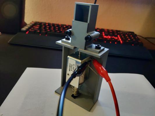
Testing the 70155K112 solenoid
The second solenoid I tested was the McMaster-Carr 70155K112. This model is what I ultimately decided to use in my design and for good reason. At only 12v and with a 1/2" (12.7mm) stroke length, this solenoid was capable of ejecting the ball with no issues. The benefits don’t stop there either. It’s lightweight, short, easy to mount, comes with a return spring, and includes a second plunger type.
This model does cost an eye-watering $40 per unit but I can look the other way given just how perfectly it works in this application.
As an aside, you may have noticed the scoop was redesigned for this test. I intended to reuse the scoop but that didn’t work out in practice as the bolts holding the original together conflicted with this solenoid’s bracket. I could have just removed the lower two bolts but I also wanted test printing the scoop with a flat back as the rounded back of the original didn’t turn out well.
In case you’re wondering, I never throw away unused/broken parts like the old scoop design. I store the unused parts, brims, supports, etc. by filament brand, type, and color in the hopes of one day recycling them with a filament mulcher/extruder.
McMaster-Carr 70155K121
The McMaster-Carr 70155K121 is essentially just the continuous duty variant of the 70155K112 I previously tested. The only reason I decided to test it too was to see if the ball could still be ejected with a lower force solenoid (spoilers: it could not). Most of the smaller solenoids I could find from other suppliers were weaker than this so I decided to stop my testing here.
Next steps
Now that I’ve chosen a solenoid, I can start designing the ball trough assembly. I expect this to take a while given the geometry will be relatively complex compared to my previous assemblies but that’s not to say I won’t be posting in the interim. I’ve got a few other projects on backburner that I’ll be sharing until the ball trough prototype is ready.
Return Lane | Half Scale Pinball
The prototype
I’ve completed a first draft of the return lane assembly; although, it’s not fully tested at this time. The problem is I can’t really test the lane without having the side wall and slingshot on either side to verify the ball behaves as I’d like. For the moment, I’ve just printed and installed a single lane on a test board.
The left return lane assembly installed on a test board
The top plate of the assembly is largely cosmetic so for the final design I intend on making it more “blocky” to better fit with the 90’s DOS shooter theme of the original System Shock. I also plan on constructing the bottom plate from metal to reduce wear. I’m considering building the top plate from clear acrylic; however, I don’t have room under the playfield to add lights under it so that may be a waste.
The right return lane assembly in the playfield render
Challenges with designing in OpenSCAD
For prototyping, I heavily leverage OpenSCAD’s Boolean operations to quickly create complex shapes; however, there is no direct way to create fillets. This posed a problem for the return lane prototype as the inlane has a concave fillet where the lane divider joins the flipper return lane.
There are a few ways to accomplish a concave fillet in OpenSCAD but they each have their drawbacks:
- You can programmatically draw the curve using the 2D subsystem but this is made difficult by the lack of a built-in Bezier curve library.
- You can subtract a circle from the corner but this gets more complex when the joint isn’t 90 degrees.
- Clever use of the offset module can produce fillets but they will be applied to the entire object.
- You could draw the part in vector art software, export to SVG, and import into OpenSCAD; however, the part will no longer be parametric.
The dimensions of the machine are bound to keep changing as I refine my designs so I opted for the simplest route of simply subtracting a curve from the lane using a hard-coded ellipse. It’s not elegant and it’s not robust but it does get the job done quick so I can move on to more important assemblies.
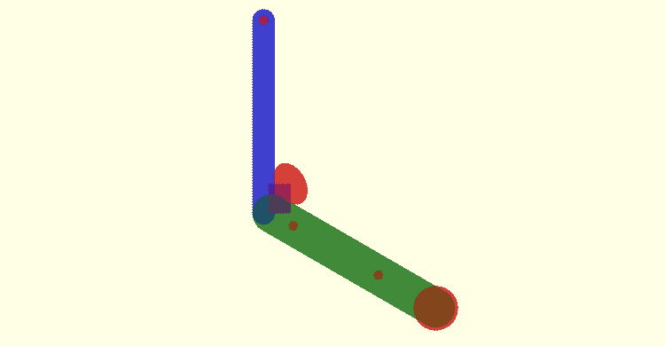
Each colored section represents a different primitive I union'd or difference'd to create the final part profile
For the final part, I’m considering writing a Bezier curve library to let me draw the curve directly in OpenSCAD. I know Bezier curve libraries already exist for OpenSCAD; however, I’m pretty opinionated with how I structure my scad files so I’d rather write the library myself to keep everything consistent. I also have bigger plans down the road to build a dependency manager for OpenSCAD so it would be helpful to have some of my own libraries I can test with.
Slingshots | Half Scale Pinball
Testing
Last post I said I’d be working on the in/out-lanes next but I finally got all the parts in to run a full test on my slingshot assembly and just couldn’t wait. The video below demonstrates the assembly with a few different general illumination colors and explains how it all works.
For this test, I just used an Arduino 4 Relays Shield and some simple code to fire the solenoid for 1/10th of a second when either sensor triggered. I also wrote in a delay forcing the solenoid to remain off for at least one second after firing to give it time to cool down (not that it gets that hot from the short burst anyways). I don’t plan on using relays to drive the solenoids in the final machine as most will require PWM signals but the Arduino is sufficient for prototyping.
Overall, I’m really happy with how the assembly turned out. That said, this is by no means the final version as there are a few quirks I need to work out.
Areas for Improvement
Unnecessary Return Spring
In the video, you can see a return spring around solenoid plunger. Theoretically, this shouldn’t be needed as the slingshot rubber can also reset the plunger; however, I found it was needed in the prototype as the slot for the slingshot actuator is slightly too short causing the actuator to get stuck without the spring.
The only reason I want to remove the spring is because it’s reducing the solenoid’s power by a fair bit. I was originally running the solenoid at 15v; however, the addition of the spring required I increase the voltage to 18v to kick the ball with the same force. Running the coil at a higher voltage isn’t ideal as it both puts more wear on the coil and requires that I run all coils at the higher voltage as well (since I do not want multiple coil voltages in the machine).
Wobbly LEDs
To make the LEDs easily replaceable, I designed custom quick-change sockets to accept standard 5mm LEDs. These sockets are great for prototyping but they don’t grip the leads tight enough resulting in the lights flickering when the solenoid kicks. This is largely because the sockets are really just holders for 2-pin Dupont connectors and the connectors I have aren’t particularly strong.
Additionally, the Dupont connectors are only friction-fit into the sockets and do fall out over time. This could be fixed with some hot glue but I’m still considering other options such as different connectors.
Deadzones
The prototype uses a pair of LJ8A3-2-Z/BY inductive probes running at 5v to detect the ball (see my previous post for more technical details). The probes are compact, easy to use, and easy to mount; however, they have a fairly small detection radius which leaves quite a few deadzones along the slingshot. The most egregious deadzone is directly in front of the kicker which means the assembly is unlikely to ever kick the ball with full force.
Unfortunately, I cannot just put another sensor in the center deadzone as the solenoid plunger would block it. I could try mounting the solenoid vertically like on a full-sized machine but even then I doubt I’d have enough space for the probe.
One option I’m considering is to shift the solenoid closer to the flippers thus giving more room for sensors; although, this would require repositioning the lower sensor further up so I’d really only be moving the deadzone. Ultimately, I don’t want to change the sensor positions just yet though as where the ball contacts each slingshot will depend greatly on the upper playfield and may make the deadzones moot (or at least move them).
Testing Inductive Probes | Half Scale Pinball
Background
One of the goals for my half-scale System Shock pinball machine is to include fully-functioning slingshots. For those unfamiliar, slingshots are the triangular kickers located just above the flippers on most pinball machines. The slingshots are designed to kick the ball diagonally up or down the playfield on contact.
This video shows a great closeup of a slingshot in action if you’ve never seen one before:
Designing half-scale slingshots that can kick was actually pretty easy; however, finding a reliable way to trigger them was a whole other problem. On a full-sized machine, the slingshots are triggered by two leaf switches located just behind the rubber ring. The slingshot is activated when the ball deflects the ring causing it to close one or both of the switches. This mechanism works great for an ~80g (~2.8oz) pinball but not so well when scaled down. Even with the softest rubber rings I could find to fit my slingshots (75A), the measly 16.3g (0.57oz) ball I’m designing for just can’t deflect the rubber far enough or with enough force to actuate most physical switches.
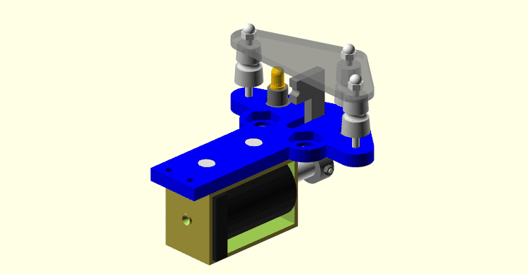
My current slingshot design for reference
To put the problem into perspective, the Gateron Clear keyswitch is one of the lightest keyboard switches you can buy at the time of writing with an operating force of just ~0.3N (0.06lb). Even with such a light switch, I would have to stack two of the 5/8" (~15.87mm) chrome steel mini pinballs just to operate it (let alone bottom it out) with the measly 0.16N (0.03lb) of force each exerts under gravity. Obviously, pinballs are going to be subject to more forces than just gravity and you can find a handful of other physical switches with lower operating forces; however, switches with such low operating forces often require excessive actuation distances or are too sensitive to vibration to use in close proximity to solenoids. I do know of one physical switch that can be reliably activated by the mini pinballs; however, that’s a topic for another day and it won’t work in this context anyway.
As I mentioned in my first post, physical switches are far from the only option for detecting the mini pinballs. Ultrasonic, infrared, and capacitive among others are all good candidates but for this post I will focus on inductive sensors. I specifically want to investigate the use of standard industrial inductive probes like you’d find on a 3D printer.
The Probes
There are plenty of inductive probes available from electronics suppliers but I chose to limit testing to two specific models: LJ8A3-2-Z/BY and LJ18A3-8-Z/BX. Why? The main features I like about these models are they’re easy to mount, trivial to interface with, and have flexible voltage ranges. It also helps they happened to show up on Amazon while I was browsing other parts. The main differences between the models are their size and maximum detection range. The LJ8A3-2-Z/BY advertises a range of only 2mm while the LJ18A3-8-Z/BX boasts an 8mm range at the expense of a much larger footprint.
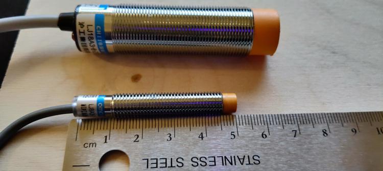
Size comparison of the LJ8A3-2-Z/BY (bottom) and the LJ18A3-8-Z/BX (top)
Both sensors connect using only three wires: power (brown), ground (blue), and signal (black). Questionable wire coloring aside, both sensors are rated for an input voltage of 6-36v and will output a signal when metal is detected in front of the orange cap (or lack thereof in the case of the LJ18A3-8-Z/BX). The maximum range at which the sensors trigger is fixed regardless of the input voltage or at least that’s what the manufacturer claims…
Curiously, I discovered by mistake that running the probes below their rated voltages can nearly double the detection range in some cases. For example, running the LJ8A3-2-Z/BY at only 4v resulted in it consistently triggering at 4mm instead of the claimed 2mm. Unsurprisingly, there is a consequence to running these probes out of spec but it’s worth the tradeoff in my opinion and something I’ll discuss later in this post. I couldn’t tell you if this behavior is common to all inductive probes but I’ve found it to be incredibly helpful and is the main reason I’m writing this post.
Testing Detection Range
Knowing the detection range of each probe changes with voltage, I wanted to run tests to measure the extent of this affect; furthermore, I wanted to measure how far the mini pinball would have to pass over sensor before it was detected.
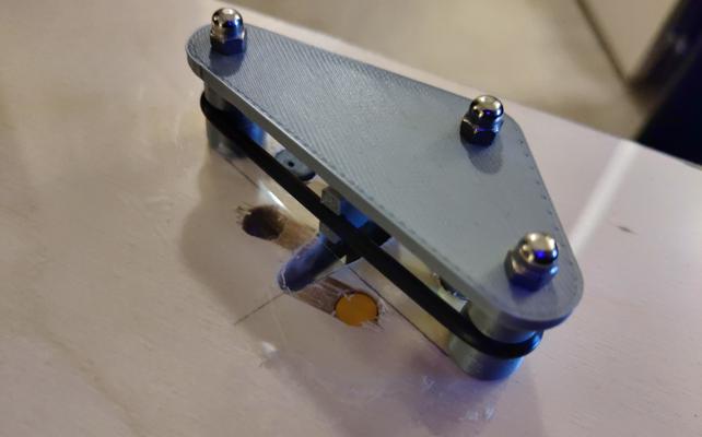
For testing, I first printed test jigs to align each probe and ball to the same height and let me slide the sensor closer to the ball along a ruler at various horizontal offsets from the ball. I then placed the ball at a known position along the ruler. For each combination of sensor, input voltage, and horizontal offset I would slide the sensor toward the ball until my multimeter showed the sensor had triggered. I would repeat the test a few times to verify consistency then record the distance between the edge of the ball and tip of the sensor.
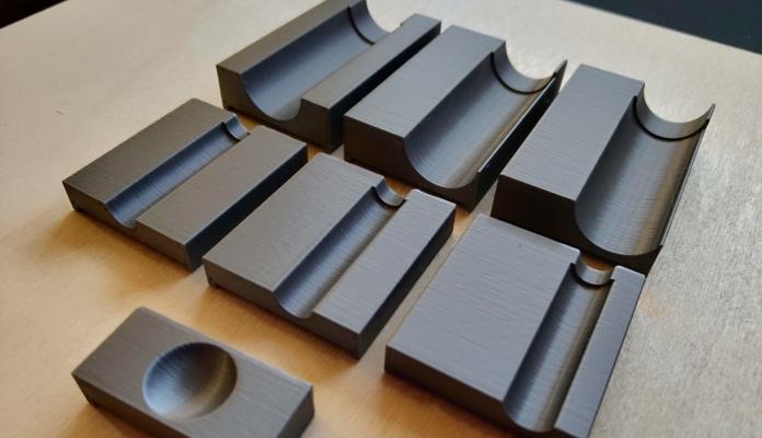
The test jigs
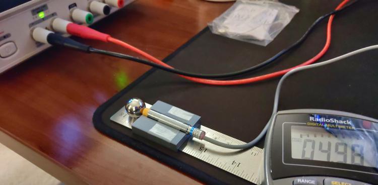
The sensor range test setup
Each sensor was tested at its lowest stable voltage, 5v, and 12v. I opted to not test at any higher voltages as I’m expecting to have power supply rails for 5v and 12v in the final machine but the only rail I’m planning with higher voltage is for driving coils and I don’t think it wise to run sensitive electronics off the same rail.
Each sensor was tested at three horizontal offsets:
- (A) Ball center aligned to the sensor cap’s center (no offset)
- (B) Ball center aligned to the edge of the sensor cap
- (C) Ball edge aligned to the sensor cap’s center
LJ8A3-2-Z/BY
4v was the lowest I could reliably operate this probe. At 3v, the sensor would trigger but not stop once metal left its detection area.
| Sensor Voltage (v) | Horizontal Offset (mm) | Max Detection Distance (mm) |
|---|---|---|
| 4 | 0.00 (A) | 4.0 |
| 4 | 3.25 (B) | 3.5 |
| 4 | 7.94 (C) | 1.0 |
| 5 | 0.00 (A) | 2.0 |
| 5 | 3.25 (B) | 1.0 |
| 5 | 7.94 (C) | - |
| 12 | 0.00 (A) | 2.0 |
| 12 | 3.25 (B) | 0.5 |
| 12 | 7.94 (C) | - |
LJ18A3-8-Z/BX
5v was the lowest I could reliably operate this sensor. The sensor would not trigger at lower voltages.
| Sensor Voltage (v) | Horizontal Offset (mm) | Max Detection Distance (mm) |
|---|---|---|
| 5 | 0.00 (A) | 7.0 |
| 5 | 7.94 (C) | 4.5 |
| 5 | 8.25 (B) | 4.5 |
| 12 | 0.00 (A) | 6.0 |
| 12 | 7.94 (C) | 3.5 |
| 12 | 8.25 (B) | 3.0 |
Testing the Effects of Solenoid Interference
While prototyping the slingshot, I found activating a solenoid close to a probe would cause the probe to trigger. This wasn’t really concerning for the slingshot assembly on its own since I could just ignore the false activation in code but I was worried nearby unrelated probes might also trigger.
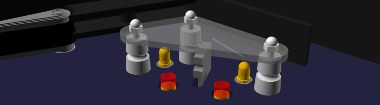
To test just how far away a probe would need to be to avoid interface, I first taped each probe to a known position on my ruler. I then placed my test solenoid (model A420-065573-00) along the ruler and fired it at different voltages while watching the probe’s output. If the probe falsely triggered, I would move it half a millimeter away and repeat until it no longer triggered. I repeated this test using the same probe voltages as my previous test and with three different solenoid voltages as I haven’t yet decided the final voltage for the game. Furthermore, I ran this test both with the solenoid facing the probe and with it beside the probe to determine how much the orientation mattered.
Interference test setup (face)
Interference test setup (side)
For each probe voltage, solenoid voltage, and solenoid orientation, I recorded the maximum distance I found interface as well as the minimum distance I found the probe to be clear of interface. The distance measurements were taken from the faceplate of the solenoid to the center of the probe and from the side plate of the solenoid to the center of the probe.
Hyphens in the following tables indicate configurations were I was unable to get the probe to falsely trigger even when directly touching the side of the probe to the solenoid.
LJ8A3-2-Z/BY
| Sensor Voltage (v) | Solenoid Voltage (v) | Max Face Interference Distance (mm) | Min Face Clear Distance (mm) | Max Side Interference Distance (mm) | Min Side Clear Distance (mm) |
|---|---|---|---|---|---|
| 4 | 12 | 2.0 | 2.5 | 1.0 | 1.5 |
| 4 | 15 | 3.0 | 3.5 | - | - |
| 4 | 18 | 3.5 | 4.0 | - | - |
| 5 | 12 | 1.5 | 2.0 | - | - |
| 5 | 15 | 1.5 | 2.0 | - | - |
| 5 | 18 | 1.5 | 2.0 | - | - |
| 12 | 12 | - | - | - | - |
| 12 | 15 | - | - | - | - |
| 12 | 18 | - | - | - | - |
LJ18A3-8-Z/BX
| Sensor Voltage (v) | Solenoid Voltage (v) | Max Face Interference Distance (mm) | Min Face Clear Distance (mm) | Max Side Interference Distance (mm) | Min Side Clear Distance (mm) |
|---|---|---|---|---|---|
| 5 | 12 | - | - | - | - |
| 5 | 15 | - | - | 1.0 | 1.5 |
| 5 | 18 | - | - | 1.0 | 1.5 |
| 12 | 12 | - | - | - | - |
| 12 | 15 | - | - | - | - |
| 12 | 18 | - | - | - | - |
Results
Ultimately, these tests have given me confidence that undervolting my sensors won’t be a major issue. The increased range (especially for the LJ8A3-2-Z/BY) is extremely valuable and I don’t expect it to be difficult to keep probes more than 4mm away from other assembly’s solenoids to avoid interface. I did find it interesting though that neither probe could be falsely triggered when run at 12v. This leads me to believe the probes are only susceptible to interference when run outside their rated voltage; although, I admittedly didn’t test within the lower end of their specifications.
All that said, the range of the probes is still a concern. Something to consider is these probes are too long to be mounted on top of the playfield which means they’ll have to be mounted under it. Even the best probe configuration I tested can still only detect up to 7mm but my playfield is already 1/4" (6.35mm) thick and that’s excluding the vinyl artwork. I could drill holes into the playfield and mount the sensors flush with its surface; however, it would be difficult to get a close enough fit to not cause the ball to jump when passing over.
The slingshot design with inset sensors. The wider hole is necessary to accommodate the probes' threads. The red cylinders represents the detection area.
This problem bothered me for a few days but I think I finally landed on a decent solution. By overlaying the playfield with a thin sheet of stiff polycarbonate 1/32" (~0.8mm), I can freely drill holes for the sensors in the wood layer while keeping the plastic play surface smooth. This solution comes with a few fringe benefits as well. Applying the playfield graphic under the plastic will help to protect it from the ball in much the same way Mylar film is used to protect full sized machines. This also allows me to hide the sensors if I attach the artwork to the back of the plastic rather than the wood.
If it weren't for the reflection, you'd hardly know there was a plastic layer here. You'll have to excuse the tape and jagged holes. This prototype has been through a lot of iterations and poorly measured cuts.
Next Steps
I worry the sensors may still not have a wide enough radius to detect the ball reliably in game; however, I won’t know for sure until I finish the lower-third and can start play testing. If you’re not familiar, the lower-third is the literal lower 1/3rd of the playfield and includes the major assemblies: flippers, slingshots, the shooter lane, drain, and in/out lanes. I already have working prototype flippers and rough designs for the drain and shooter so next up are the lanes.
Half Scale Pinball
Background
Since 2015, I’ve been working to build a roughly half-scale pinball machine themed after the original System Shock. I got the idea from the various mini-pinball machines built on the Ben Heck Show [1] [2] and from having finished playing the original System Shock around the same time. This whole idea started when I noticed the serv-bots on the medical level closely resembled pinball pop-bumpers. From there, I began to think about how many of the objectives and mechanics in the game could be adapted to modes in a pinball machine.
Pop bumper and Serv-Bot together at last
While the project is far from complete, I’ve decided to start blogging my progress to help anyone else in the community wanting to build their own scaled down pinball machine. The world needs more mini-pinball!
Objectives
From the start, I knew my machine had to be fully featured. To me that means, all of the following mechanisms must be present and they must work more-or-less the same as those found on full sized machines:
- Auto-plunger
- Backglass
- Coin-mech (that only accepts dimes)
- Dot Matrix Display
- Drop Targets
- In/out Lanes
- Kick-out Hole
- Light Strips
- Multiball
- Playfield Inserts
- Pop Bumpers
- Rollovers
- Skill Shots
- Slingshots
- Spinners
- Tilt Sensor
I don’t know how feasible all of these features are but I strive to at least try each one. Additionally, I have a few general goals I’d like to achieve for my own peace of mind:
- Minimal high-voltage wiring
- Consumable components are easily replaceable
- All playfield mechs are designed to be reusable in other games
- Minimal custom PCBs
- Use as many original game assets as possible
- Avoid servos (I just really hate that high-pitch sound they make)
I have a few special features I’m designing in as well but you’ll just have to stay tuned to future posts to hear about those.
Challenges
One of the first and most persistent challenges of building a scaled down pinball machine is the OG buzzkill, physics. As Ben noted in his show, simply scaling down the ball’s diameter by half doesn’t really work all that well as you lose so much mass that the ball becomes uncontrollable. Taking Ben’s advice, I have chosen to use a 5/8" bearing ball as opposed to a 1/2" ball.
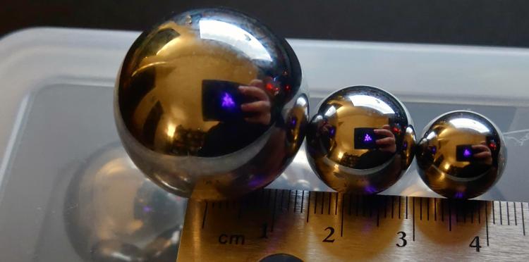
From left to right: 1 1/16" (~27mm), 5/8" (~15.87mm), and 1/2" (~12.7mm) bearing balls
Even with the adjusted diameter, the 5/8" ball just doesn’t have enough mass to actuate most switches. As an experiment, I tried resting one of the mini pinballs on a Cherry MX Speed switch and to my horror it didn’t even begin to depress the switch. As others have demonstrated in their own scaled pinball projects, this limitation does have workarounds but it requires some creative use of alternative sensor types (eg capacitive, infra-red, inductive, etc.).
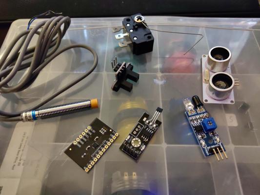
Sensors I've tested thus far including capacitive, inductive, optical, Hall effect, physical, and ultrasonic
Physics isn’t the only problem we’ve got to contend with either. Finding solenoids with enough power and throw to actuate the playfield mechs has been far more difficult than I initially expected. Most higher power and longer throw solenoids are simply too big to fit into a half-scale cabinet and smaller solenoids lack the power or range needed to do anything useful. Thankfully, I’ve found this can be mitigated by overvolting smaller solenoids; although, only time will tell how long the solenoids last being driven at 150-160% their rated voltage.
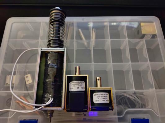
Pictured above are 3 vastly different sizes of 12v solenoids
Development
I personally prefer to work in CAD before making anything physical. I realize this is completely backwards from nearly everyone else; however, I find I just can’t picture the end result I want without drawing it out in CAD first. In a twist that’s sure to surprise some, my CAD tool of choice OpenSCAD. The reason for this is twofold: 1) OpenSCAD’s language really meshes with how I think (pun intended) and 2) Fusion 360 is borked for my Autodesk account and I refuse to make a new account just to fix their software.
In all seriousness, I have used Autodesk 3D modelling and CAD software in the past but being a software engineer by trade I just feel more comfortable writing code. That said, OpenSCAD leaves a lot to be desired (especially in the dependency management front) and I probably would have been a lot farther along by now had I forced myself to use something else. All that’s to say: your mileage may vary.
Current Progress
Unsurprisingly, that laundry list of features, challenges, and my odd choice in toolchains hasn’t resulted in the progress you’d expect to see after 7 years; however, that’s not to say I’ve been slacking either. I’ve made great strides in improving my development workflow with OpenSCAD libraries, tested numerous mech prototypes and sensors, and produced working assemblies for the flippers, slingshots, and drop targets. The screenshots below are renderings of some of the current progress and there will be more to come in future posts.
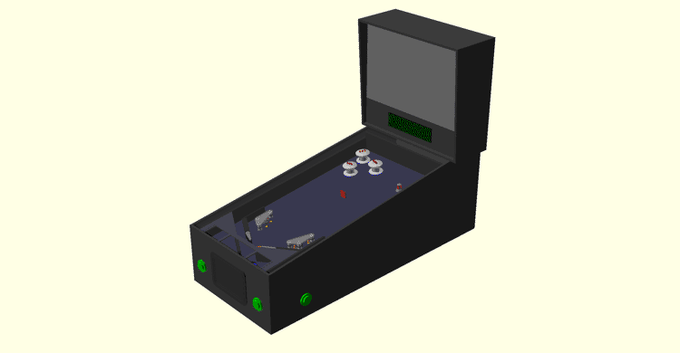
A look at all the designed parts in a mockup cabinet
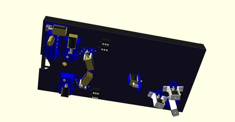
The current underside of the playfield
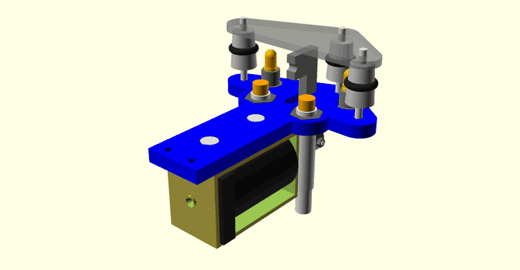
Closeup of the slingshot assembly without the playfield (rubber ring not shown)
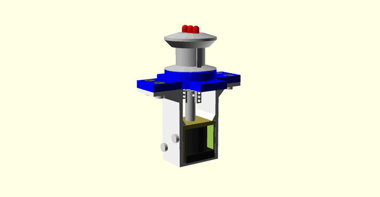
Closeup of the WIP pop bumper assembly
Wrap-up
That’s all I’ve got time to write about for now but be sure to subscribe to my RSS feed so you get notified of my future progress. In the short-term, I’m planning in-depth posts on the mechs built thus far and the challenges I faced designing them.
Game Jams
A surreal racing experience for GMTK Jam 2025 | InsomnaKart
Here we go again
As part of my effort to participate in more game jams this year, I entered GMTK Game Jam 2025 immediately following Kenney Jam 2025. Unlike Kenney Jam, going in, I didn’t have a strong desire to make any particular genre; however, I did know that despite being a four day jam, I wouldn’t be able to work more than about two days due to other obligations.
Planning
When “loop” was announced as the theme, I started with a mind-map and widdled that down to just two ideas:
- A racing game where you’re trying to hit obstacles on the track (heavily inspired by the rush hour mode of Jak X: Combat Racing)
- An RTS with a tech tree where time resets when you die but you keep all your materials allowing you to advance more each run
Having just finished my Riverworld modding tools, I really wanted to make an RTS but decided the content and AI would be too much for me in 48 hours. The racing game seemed easier since it didn’t necessarily require AI.
Being a fan of Jak X, and the intense sense of speed it gives, I decided to mimic its controls for my game. To that end, I planned for a boost mechanic which I would encourage players to use by multiplying the score of a hit obstacle with each lap and a power-slide mechanic which would be required to navigate hairpin turns in the track. I also planned for a weapon power-up which would give the player a larger hitbox on demand; however, this was ultimately cut for time.
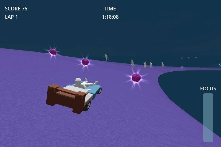
Final gameplay
Development
Architecture
Like Maximum Voltage, I heavily leveraged a component-based architecture for my game; however, I decided to try a different approach to components that I had seen in a YouTube video. With my previous games, each component was its own class which often led to duplicate code for components that reacted with an area in the environment. For example, Maximum Voltage’s battery pickup and intel pickup components both had logic to kill an attached health component on activation. Based on this, I decided to apply a behavior-based pattern to interactable components in this game.
I created a base InteractionComponent which would detect a collision with an area and pass the area to a custom behavior resource’s interact_with method. The base component had all the logic to disable itself on use but deferred to the custom behavior resource for what would actually happen when it was triggered. I used this system to implement checkpoints, boost pickups, and the out-of-bounds respawn. In theory, this seemed like a good idea but in practice it made the code more complex for little benefit.
The main problem with this pattern is there’s no good way to connect the custom behavior resource to other components of the parent object. For example, the out of bounds component ideally needs a reference to the player it is attached to so it can trigger a respawn but it isn’t easy to pass a reference to the player node into a resource since that resource then becomes scene-local and can only use node path references. For similar reasons, the parent object can’t easily connect to events from the behavior if the behavior was created through the UI. It’s not impossible to do with this pattern but is messier than I’m personally comfortable with.
I think this new pattern has merit in systems where the base component has references to everything the behavior could need (ex where the behavior describes a type of projectile, spell, etc) but I don’t think this pattern works as well when each behavior has dependencies on different things.
Player controllers
Movement
The player movement is largely based on the KidsCanCode Arcade Style Car but I did make a few changes:
- Tweaked various base physics settings
- When reversing, the steering direction is inverted
- The maximum speed is limited using the
_integrate_forcesfunction - The turn speed, angular damping, and amount you can accelerate and turn is modified when power sliding
- The maximum speed is increased when boosting and the acceleration is instantly max’d out
This worked relatively well but I did find it very difficult to tune given the number of parameters available. It also has an annoying quirk that the player will slowly slide off sloped surfaces.
Camera
Even while boosting, the player never actually moves that fast. Instead, the sense of speed comes from a few camera tricks I learned from playing Jak X during the jam.
Since the game is running in Godot’s compatibility mode, effects like camera blur aren’t available. Normally, I’d mess with the camera’s FOV to give the impression of speed but I noticed Jak X has the same limitations but a different solution. Instead, at a certain speed threshold it drops the camera lower to the track. Because the track is textured, getting closer to it makes it look like it’s moving by quicker. This effect was very easy to implement and I find to be less jarring than altering the FOV.
The next trick is having the camera pan left/right from a point in front of the car/bed while turning. I defined a curve which, based on how fast you’re going, determines how far in the opposite direction the camera will pan while turning. Since the camera pans from the front of the car, it gives the effect that you’re drifting more than you actually are and gives a sense of weight to the car.
Checkpoints
Based on how I’ve heard other racing games work, I implemented a checkpoint system to determine whether the player legitimately completed a lap. Along the track are Area3Ds which you must pass through in sequence to activate the next. A checkpoint will not register if it is not active and will not become active unless the previous checkpoint was passed. Passing the last checkpoint triggers a signal that a lap was completed and starts the sequence over.
The same checkpoints are also used to trigger the enemy spawners located along the track. This was meant to help pace the enemy spawns but didn’t work so well in practice.
This system was incredibly simple to implement and would have served to help with player respawns if I had time to finish that system (as-is, the player always respawns at the start of the lap). I definitely want to explore this system more in future games!
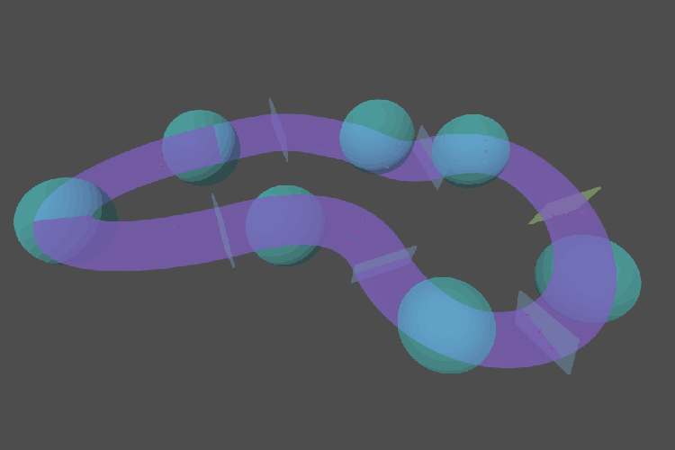
Each rectangle is a checkpoint and the spheres are enemy spawners
Design pivot
Saturday afternoon, I had all the gameplay features implemented and asked my friend James to help with beta testing. Right away, I realized there was a problem when I had to explain that your goal was to hit the memories rather than dodge them. There was no obvious connection to the theme to guide the player to that objective nor did I have time to make a cutscene.
As James played, he noted that he was having difficulty aiming for the memories. At the same time, I was playing and noticed I was gravitating towards dodging memories to get higher lap multipliers rather than trying to hit them. At that moment, I realized the core concept was flawed and that it would be more fun and better aligned with the narrative to have the player dodge the memories.
Thankfully, the component architecture made it easy to move scoring to the boost pickups and within a couple of minutes I had a new build which was much more fun to play. Unfortunately, I think I was still too hung-up on the scoring system to recognize that I should have made other gameplay changes but I’ll save that discussion for the post-mortem section.
Time allocation
Unlike Kenney Jam 2025, I didn’t bother putting together a schedule since I wasn’t sure exactly how much time I’d have to work on it; however, I did track my time throughout the jam for those curious.
Expand devlog
- Wednesday
- 12:15: Project setup
- 12:25: Theme planning
- 13:48: Break
- 19:03: Planning
- 19:11: Player controller
- 20:04: Learning how to import/retarget animations
- 20:50: Sleep
- Thursday
- 21:00: Camera controller
- 23:02: Finding music
- Friday
- 00:12: Checkpoint component
- 02:00: Interaction component
- 02:30: Player controller
- 03:30: Sleep
- 19:10: Game events
- 20:00: Break
- 23:00: Pushable component
- 23:20: Health/death components
- 23:30: Score component
- 23:36: Game timer
- Saturday
- 00:00: Enemy animation
- 00:14: Break
- 01:20: High score system
- 02:00: Sleep
- 10:00: Boost & game feel
- 10:56: Boost pickup
- 11:45: Lunch
- 12:00: Boost pickups
- 12:31: Track
- 13:08: Break
- 13:45: Enemy AI
- 13:50: Break
- 15:10: Enemy spawner
- 15:30: Game feel
- 17:53: Beta testing
- 19:53: Polish visuals
- 21:48: Break
- 23:00: Menus
- Sunday
- 03:00: Audio
- 03:59: Visual effects
- 05:00: Bug fix
- 05:15: Break
- 06:09: Visual effects
- 08:00: Polish
- 09:39: Jam page
- 11:28: Done
Expand time summary
| Task | Details | Minutes |
|---|---|---|
| Planning | Ideation | 83 |
| Planning | Schedule | 8 |
| Planning Total | 91 | |
| Project Setup | Godot setup | 10 |
| Project Setup | Animation import workflow | 46 |
| Project Setup Total | 56 | |
| Code Code | Health/death components | 10 |
| Code Code | Game events | 50 |
| Code Code | High score system | 40 |
| Core Code Total | 100 | |
| Mechanics | Camera controller | 170 |
| Mechanics | Checkpoint component | 108 |
| Mechanics | Interaction component | 30 |
| Mechanics | Player controller | 113 |
| Mechanics | Pushable component | 20 |
| Mechanics | Score component | 6 |
| Mechanics | Game timer | 24 |
| Mechanics | Boost pickup | 136 |
| Mechanics | Enemy AI | 5 |
| Mechanics | Enemy spawner | 20 |
| Mechanics Total | 632 | |
| Game Loop Bookends | Menus | 240 |
| Game Loop Bookends Total | 240 | |
| Level Design | Level design | 37 |
| Level Design Total | 37 | |
| Beta Testing | Beta testing | 120 |
| Beta Testing Total | 120 | |
| Bug Fixes | Bug fix | 15 |
| Bug Fixes Total | 15 | |
| Balance | Game feel | 143 |
| Balance Total | 143 | |
| Audio | Audio | 59 |
| Audio | Finding music | 22 |
| Audio Total | 81 | |
| Polish | General polish | 99 |
| Polish | Visual polish | 301 |
| Polish Total | 400 | |
| Jam Submission | Itch page & Submission | 109 |
| Jam Submission Total | 109 | |
| Break | Break | 819 |
| Break | Sleep | 2870 |
| Break Total | 3689 | |
| Total | 5713 | |
| Dev Total | 2024 (35% of allotted time) |
Tellingly, I managed to spend 5 fewer hours working on this game than my submission for Kenney Jam 2025 despite having double the time limit.
Post-mortem
Results
Of the 9,643 final entries and 197k ratings, I received 25 ratings and the following ranks in each category:
| Category | Rank | Rating |
|---|---|---|
| Narrative | #1502 | 3.00 / 5.00 |
| Enjoyment | #3667 | 2.96 / 5.00 |
| Creativity | #3875 | 3.28 / 5.00 |
| Audio | #4461 | 2.64 / 5.00 |
| Artwork | #7159 | 2.16 / 5.00 |
I actually didn’t think my narrative was all that clear this jam so I’m incredibly shocked that I ranked in the top 16% for that category! Despite not ranking that high in enjoyment or creativity, I am also really happy to see that my ratings weren’t too bad.
The most common feedback I got was that people liked the humor/narrative and thought the game was fun; however, many felt the steering and braking weren’t responsive enough and that it was too hard/unfair to dodge the memories. Based on the rankings, I can also see that audio and visuals were not well received which isn’t surprising given I didn’t leave myself enough time at the end to polish them.
You can play IsomnaKart on Itch.io but I recommend some of my favorite submissions instead:
Observations
Being the first time I’ve taken place in the GMTK jam, I thought I’d take some notes about how it differs from the other jams:
- Nearly every category winner was download-only - my previous experience has been that downloadable games don’t do as well
- Only half of the category winners were made by teams
- The level of polish for winning games was nearly the same as commercial releases
- Most people were not, or at least did not appear to be, using pre-made assets
- Most games were much longer than 3-5 minutes - some even taking half an hour or more to complete
Pros and cons
Pros
- Recognized the original concept wasn’t engaging and pivoted to what felt fun
- Slide/boosting around corners and off edges is extremely satisfying
- Love how the brain pickups look
- The Godot Road Generator plugin worked flawlessly
- Audio levels were correct this time
- I think having a gif on the jam page helped explain the gameplay
Cons
- Game was severely underpolished even by 48 hour jam standards
- The intro cutscene is awkward and jank
- Connection from the theme to the gameplay isn’t great
- Impossible to dodge without holding boost
- The way I intended the game to be played isn’t obvious to everyone (ie holding boost all the time)
- Random spawns meant not everyone had a good first experience and made the skill ceiling low as scoring high is purely random
- There isn’t much score variation between runs making it feel like you can’t improve
- Using an in-editor thumbnail for the submission page just doesn’t look that good
- I spent way too much time taking breaks
What I would do different
I believe I was right to pivot the game idea when I did but in hindsight I don’t think I pivoted enough.
When the game was based on hitting the memories, the heavier steering, random enemies, and score-based gameplay made more sense since you wanted to hit as many as possible. When changing the game to avoid memories, I should have also made the steering more responsive and the enemy spawns more predictable so dodging was skill-based.
I also think it was a mistake to stick to score-based gameplay. It would have fit better with the narrative to have the game be a time-trial where you’re trying to complete x laps as fast as possible. I could have also changed the timer to count up from midnight to the morning to represent your character struggling to fall asleep.
Artistically, I really want to make games that look and feel like they were released for the PS2 which is why I used one of the PS2’s resolutions for this project; however, the pre-made assets I was using just don’t look as good at that resolution without more advanced visual effects like tilt-shift and dynamic lighting. This is something I already knew but neglected for this jam. Until I can make my own PS2-style assets, I should probably stick to more retro-inspired theming since it works better with the simpler assets I have access to.
With the jam page, I want to get away from using in-editor screenshots for the thumbnail. It just doesn’t look as polished as what others are producing and I beleive it’s limiting how many people choose to play my games.
All that said, I’ve got other projects I want to spend my time on so I won’t be updating InsomnaKart but I will try to remember this for the next jam.
I made a rail shooter for Kenney Jam 2025 | Maximum Voltage
Practice. Practice. Practice.
Since Scream Jam 2024, I’ve been creating tons of small prototype projects in Godot to better learn the engine’s features. Since I wanted to focus on the coding, I’ve been using Kenney assets exclusively for these projects so I was really excited when I learned that Kenney has a yearly game jam!
Preparation
After not doing so well in my last 7 day jam, I was extremely nervous to try a 48 hour jam but decided to make the best of my time by reviewing Adam Younis’ jam devlogs for tips before the jam. I took away two points from his devlogs: make a schedule and prioritize tasks. To that end, I put together my own general purpose schedule for a 48 hour jam based on my best guess at how long each task would take. The exact time spent on each task isn’t that important but the order I work on them was carefully chosen to get the game playable as early as possible.
Expand schedule
Day Time Goal Actions Friday 11:00 AM Ideation Brainstorming - Concept Design Friday 12:00 PM Systems Mechanics - Core Loop Friday 01:00 PM " Friday 02:00 PM " Friday 03:00 PM " Friday 04:00 PM Game Playable Friday 05:00 PM World Design Friday 06:00 PM Core Animations Friday 07:00 PM Game Loop Bookends Score - Win Condition - Loose Condition Friday 08:00 PM Level Design Friday 09:00 PM " Friday 10:00 PM " Friday 11:00 PM " Saturday 12:00 AM " Saturday 01:00 AM UI Design Saturday 02:00 AM " Saturday 03:00 AM Game Complete-able Saturday 04:00 AM Juice Saturday 05:00 AM " Saturday 06:00 AM " Saturday 07:00 AM Story Saturday 08:00 AM SFX Saturday 09:00 AM " Saturday 10:00 AM Music Saturday 11:00 AM " Saturday 12:00 PM Beta Test Saturday 01:00 PM Collectables/Extras Saturday 02:00 PM " Saturday 03:00 PM " Saturday 04:00 PM Title Screen Saturday 05:00 PM Settings Menu Saturday 06:00 PM Credits Saturday 07:00 PM Cutscenes Saturday 08:00 PM " Saturday 09:00 PM " Saturday 10:00 PM Create itch Page Saturday 11:00 PM " Sunday 12:00 AM Testing Test Game in itch Sunday 01:00 AM Create thumbnail Sunday 02:00 AM Screenshots Sunday 03:00 AM Submit Sunday 04:00 AM Sunday 05:00 AM Sunday 06:00 AM Sunday 07:00 AM Sunday 08:00 AM Sunday 09:00 AM Sunday 10:00 AM Sunday 11:00 AM DEADLINE
After building the schedule, I finished my prep for the jam by downloading every Kenney and Kay asset pack and importing them into a file manager called Eagle. Eagle is a program I learned about last year from a YouTube video on tag-based filesystems and I’ve been using it ever since to help organize my game assets (not sponsored, I just really like it). The nice thing about Eagle is that it lets you assign tags to your assets and search for them much easier than through Windows Explorer. I figured having the files indexed would help me find what I need during the jam quicker.
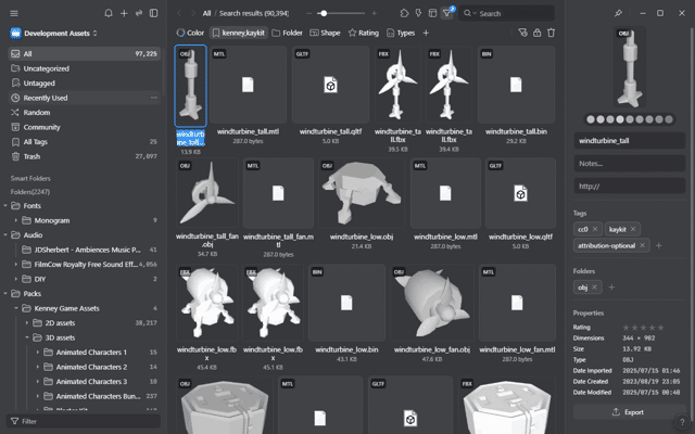
Searching for Kenney and Kay assets in Eagle
Ideation
Before the jam started, I had been on a rail-shooter kick playing games like Starfox 64 and Galaga: Destination Earth. Having seen the ships in the Kenney Space pack before, I really wanted to try making a game like these and was thankful when power was announced to be the theme. Immediately, I decided that I would build a 2-3 minute rail shooter where the player fires electrical bolts and can charge their ship to either unleash a more powerful attack or dodge. I figured this idea was perfect for a short jam since player and enemy movement could be done entirely with Path3D nodes.
Being inspired by retro rail shooters, I also decided the game would run in an extremely low resolution (256x224) and adhere to the simple geometry and colors of a SNES SuperFX game.
Development
Component architecture
I’ve been working to embrace component architecture more in my recent games so I started by defining a whole set of reusable components for every game function I could need: health, hitboxes, hurtboxes, scoring, item pickups, damage/hit effects, etc. These components are so generalized that almost every object in my game was built from the same components.
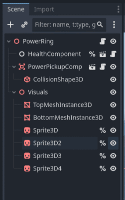
Charge ring components
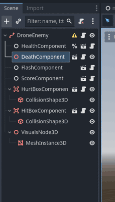
Enemy components
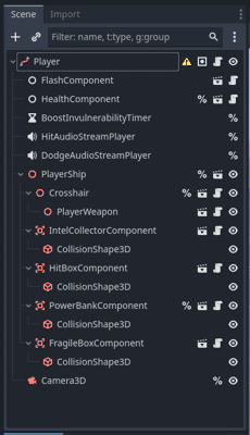
Player components
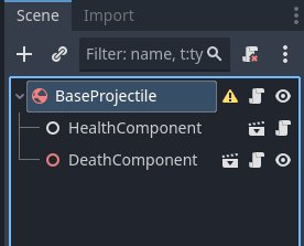
Projectile components
Most components are also written in such a way that they can take references to other components to chain behavior without needing any code. This is done by having the components self-subscribe to the linked component’s signals on ready. For example, the pickup component will kill a linked health component when obtained and the death component will destroy an object when its linked health component is killed.
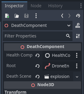
Example death component
Example flash component
Example hit-box component
Example hurt-box component
Example score component
Player controllers
Both the player and enemy inherit from a custom PathFollow3D node called RailFollower which adds extra logic to follow a path at a set speed.
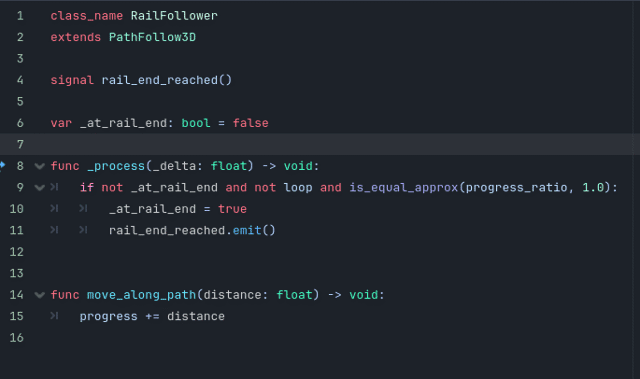
Rail follower
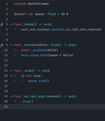
Enemy code
The player ship doesn’t directly follow the path but rather is constrained to a 3D plane following the path; unfortunately, it gets a bit more complicated still. I learned that to look correct, the ship actually needs to pitch and yaw away from the camera as it reaches the extents of the screen. That caused problems for the aiming since I implemented the crosshairs as literal 3D objects attached to the front of the ship. Having the ship pitch/yaw as it moves caused the crosshairs to go off screen and required a lot of manual tuning to fix.

Player scene showing the crosshairs in front
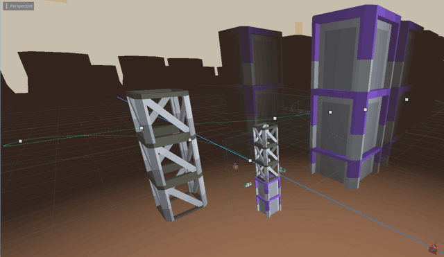
Player and enemy paths
Rendering
Several people in the jam comments assumed I was using a shader to pixelate my game but the reality is much simpler. I just set the project’s window resolution to 256x224, enabled viewport scaling, and switched it to integer upscaling. The game is natively rendering in 256x224 and the pixel size just gets multiplied for larger windows.
This has the downside of causing the game to be very small by default; however, I used Itch.io’s canvas size option in the game settings to force the canvas to a larger initial size.
Time allocation
To help with my planning for future jams, I recorded my time throughout the jam:
Expand devlog
- Friday
- 11:00: Project setup
- 11:15: Ideation
- 12:15: Rendering
- 12:22: Rail follower / camera
- 13:20: Player movement
- 13:38: Targeting reticule
- 14:32: Bug fix
- 16:00: Hit box / health components
- 17:00: Laser components / spawn manager
- 18:40: Break
- 19:40: Basic enemy
- 20:20: Gameplay tweaks
- 23:20: Break
- Saturday
- 00:03: Scoring system
- 01:19: Power system
- 02:44: Break
- 03:16: Add turbo laser
- 04:30: Add boost
- 04:45: Enemy spawner
- 05:00: Trigger volumes
- 05:30: Fixing shader stutter
- 05:51: Game balance
- 06:00: Bookends
- 07:00: Break
- 07:40: Jam page
- 08:05: Break
- 12:38: Bookends
- 16:23: Beta testing
- 17:53: Transitions
- 18:35: Bug fixes
- 18:39: Game over screen
- 21:55: Level design
- Sunday
- 00:55: Break
- 01:39: SFX
- 02:55: Visual design
- 03:56: Break
- 04:20: HUD
- 05:49: Splash screens
- 06:43: Credits
- 08:17: Store page
- 10:00: Submission
- 10:14: Fix sound bug
- 10:17: Done
Expand time summary
Task Details Minutes Planning Ideation 60 Planning Total 60 Project Setup Godot setup 15 Project Setup Total 15 Core Code Rendering code 7 Core Code Shader preloader 21 Core Code Total 28 Mechanics Movement code 18 Mechanics Camera 58 Mechanics Crosshair 54 Mechanics Projectile system 100 Mechanics Hit box / health components 60 Mechanics Drone enemy 40 Mechanics Power system components 85 Mechanics Dodge 15 Mechanics Turbo laser 74 Mechanics Scoring system 79 Mechanics Enemy spawner 15 Mechanics Trigger volume component 30 Mechanics Total 628 Game Loop Bookends Level reset code 60 Game Loop Bookends Menu code 225 Game Loop Bookends Game over code 196 Game Loop Bookends Total 481 Level Design Level design 180 Level Design Total 180 Beta Testing Beta testing 93 Beta Testing Total 93 Bug Fixes Bug fixes 95 Bug Fixes Total 95 Balance Gameplay tweaks 180 Balance Score balancing 9 Balance Total 189 Audio SFX 76 Audio Total 76 Polish Scene transitions 42 Polish Visual polish 61 Polish HUD redesign 89 Polish Splash screens 54 Polish Credits screen 94 Polish Total 340 Jam Submission Itch page 128 Jam Submission Submission 14 Jam Submission Total 142 Break Break 514 Break Total 514 Total 2841 Dev Total 2327 (81% of allotted time)
I’ve heard from multiple devs that a short highly polished game will do better in jams than a longer less polished game so I spent most of my time working on polish rather than the game’s level. This unfortunately meant the final level was only 30 seconds long but I think it worked to prove out the concept.
Post-mortem
Results
Of the 717 final entries, I received 22 comments and won best itch.io page.
Given the jam isn’t ranked, I wasn’t expecting to win anything with over 700 other entrants so I was blown away that I won best itch.io page.
The most common feedback I received was that the visuals, polish, enjoyment, and genre choice were great but that the game was too short, hard to determine depth, and the ctrl keybinding was conflicting with browser shortcuts.
You can play Maximum Voltage on itch.io or check out one of my favorite submission to the jam:
Pros and cons
Pros
- Components made it easy to build levels and add new behaviors
- Kenney assets look great in low-resolution
- Focusing on core gameplay first was the right move
- High-score focus makes the game more enjoyable to replay
- My strength is cinematic events so a rail shooter really highlighted that
- Including hit% in the score screen made it more fun to replay
- Rapid fire is so satisfying
- Early web testing helped identify several critical performance, audio, and sprite issues
Cons
- Spent too much time working on the menus and didn’t have enough left to finish the first level
- Difficult to tell in editor what the bounds of the player’s movement are which made level design more trial and error
- There’s no reason in the final game to use the dodge so it just feels like a waste of power and by extension the single power pickups
- Developed the game with my speakers on low so I didn’t notice until after submission the master volume was way too high
- Should have made my game manager a general purpose scene transitioner as that would have reduced code in the main menu scene
- Ctrl was a bad key mapping - it’s hard to press and I learned from a reviewer that pressing Ctrl+W closes the entire browser
- No volume slider
- Several people had issues with depth perception
- Name didn’t quite match the game
- Should have used pictures instead of headers for the jam page, shouldn’t have repeated the title in the page text after the banner
- The aim-centering is bugged and re-centers the aim on the ship not the screen making it so your ship blocks the view when shooting anything straight ahead
What’s next
Due to popular demand, I started working on several updates to the game during the judging period. While I’d like to make a full rail shooter at some point, I don’t think Maximum Voltage has enough of an identity of its own for that but I am working to complete the first level of the game as I envisioned. This means adding enemies that shoot back and more cinematic encounters.
I have a lot of jams scheduled back-to-back this year so I won’t make any promises for the release date but know that it is in the works.
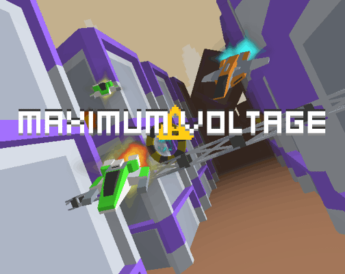
I failed Scream Jam 2024 | Negative
A recipe for disaster
After placing decently well in Scream Jam 2023, I was excited to push myself further in Scream Jam 2024. Since the last jam, I had been practicing my pixel art in daily challenges (1 2 3 4 5 6) and pushing myself to learn synthesizers. Going into the jam, I felt like I could do something more advanced than my 2023 entry and so I set myself two goals:
- Make a game that features more action
- Make all of the assets myself
But it wasn’t those goals which sunk me in the end though.
But why now?
I debated writing this post-mortem back in 2024 but I kept thinking I would eventually revisit the game so I didn’t want it spoiled. Half a year later, I’m ready to let this albatross go and talk about just where I went wrong.
The idea that never was
Story
Once the jam started, I initially decided on a game about a group of friends visiting a remote cabin in the dead of winter. As your character prepared to take a photo of the group with your instant film camera, invisible specters would cut power to the cabin and maim your friends. An errant shot from your camera would kill one specter and give you a way of defending yourself. As the cold set in, the player would discover they were locked inside by the specters and needing to quickly dispatch them before you froze.
Gameplay
As the specters would be invisible and require an exact shot from the camera to banish them, the gameplay would have centered around the player needing to find items around the cabin to help them reveal the specter’s positions. For example, I imagined breaking glass over a floor to reveal footprints where the specters were patrolling or overflowing a tub and watching for splashes on the floor. The player would have limited film so missed shots would not be an option if they wanted to survive.
The game would have been called Negative to reflect both the temperature the player was enduring as well as the film negatives integral to the gameplay.
Pivot
I really liked this idea and immediately set to work on a camera HUD and inventory system but quickly realized a glaring issue: art. While I had been practicing pixel art, I realized that I would need a lot of art to make an entire cabin not to mention all the items the player needed, animations, etc. I decided this was reason enough to pivot early and find a design that would be less taxing.
At that point, I feel like I was making the right decisions; however, it was my new idea that led to my demise.
The idea that shouldn’t have been
Story
My new idea was was still set in the remote cabin with invisible characters leaving footprints and a camera mechanic but with the twist that the player was really the monster and the footprints were being left by the cabin’s inhabitants. The whole idea being that the pale creature you play as feeds off humans by taking photos of them using a instant camera embedded in its head. To make it even more gruesome, the creature would hack up a polaroid of its victim’s last moments from its distended mouth after it’s finished digesting their consciousness.
Gameplay
Unlike the original idea, the humans would actively attack the player on sight so the gameplay would have pivoted to more of a stealth game with the creature needing to find ways to lure the humans around for better vantage points. The humans would have only been visible by their footprints to make the twist reveal less obvious at the end.
I really liked this new idea and became too attached to let it go despite it solving none of my existing issues while also creating new ones.
Art dilemma
Firstly, this new idea did nothing to address the art problem since I’d still needed a whole cabin’s worth of assets and things to draw the humans’ attention but now I also needed art for the monster twist reveal at the end.
Plot holes
Second, this new idea had tons of plot holes I couldn’t find a way to patch at the time:
- Why were the humans invisible if the creature literally has a camera for a head?
- Why don’t the humans just leave?
- How do I hide the fact that you’re a monster if you’re actively hunting things?
- And the list goes on…
Cursed game design problems
Finally, there’s a notion in game design of cursed problems: what happens when games which try to incorporate two or more mechanics that directly conflict. In my case, shifting the game to be more stealth focused fundamentally conflicted with the concept of needing to find your targets.
If the targets are invisible, how is the player supposed to avoid getting seen and attacked by them? Any visual queues for the targets would also give away their position making the trap laying mechanic useless. Similarly, if something is actively attacking you, you know where they are and can instantly photograph them.
I spent the entire rest of the jam trying to wrestle out a solution for this conundrum. I was convinced that similar games like Fatal Frame managed to make this work so I should be able to as well; however, having not actually played Fatal Frame at the time, I didn’t realize those games had wildly different mechanics from what I was trying to make despite the similar theming.
In hindsight, I can think of tons of ways to fix this both with story and gameplay but I was panicked at the time and hitting a mental block.
End of line
After several days had passed, I realized there was no way I could finish a game with the level of polish I wanted and just submitted my camera HUD proof-of-concept to the jam in defeat. A few kind folks left reviews saying they did like the concept and camera HUD but realistically, there was no game to be played.
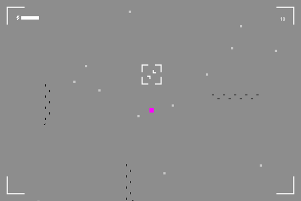
This screenshot is about as interesting as the actual "gameplay"
Turning a negative into a positive
See what I did there? Sorry, anyways…
I’ve spent a good deal of time thinking about where I could have saved this jam and I believe I finally have a decent idea. I don’t think the failure was the story or even my cursed design problems. I suspect both of those were side effects of a mistake I made much earlier on.
I believe my failure was in deciding that I needed to grow my design skills by trying action-oriented gameplay but not accepting that story couldn’t be my main focus like it was in my 2023 jam entry. Because of the feedback I had gotten in my previous entry, I felt like story was my strong suit with my gameplay severely lacking. That’s why I set the goal to focus on gameplay which I think was the right move; however, I also wanted to embrace my strengths so I couldn’t let go of making story an important factor in the game.
To be clear, I don’t think it’s inherently wrong to want to play to your strengths while trying something new. Where I feel I went wrong was in trying to make both my top priority and refusing to let one be more important than the other. When I thought of something fun to play, I should have just followed it and made the story fit the gameplay rather than letting the story I already picked overrule the game. I’ve since participated in another jam (post coming soon) where I focussed exclusively on gameplay and was much happier with the results.
A message to those who fail
You will fail at a game jam. That’s not a threat; it’s a guarantee… and it’s not a bad thing.
Failing helps you understand where you still need to learn and it’s my opinion that the longer you go without failing, the harder that pill will be to swallow. So don’t be afraid to try new things and don’t let your failures go to waste. Learn from them by doing post-mortems (just preferably, don’t wait until 8 months after).
Negative is available to “play” on Itch; however, I’d recommend checking out the other amazing submissions to the jam instead.
I made a game for Scream Jam 2023 | Consignment
An old hobby
It’s been over a decade since I last made a game solo (made in Flash CS5 if that’s any indication) and I haven’t used a proper game engine in years but with all the recent talk about Godot, it finally felt like the right time to get back into game development.
I took a look at Godot 3 a few years ago; however, I just couldn’t bring myself to sit down and learn it. I’ve since learned one of the best sources for motivation is to hold yourself accountable to someone else’s timeline which is why this year I decided to enter into Scream Jam 2023 and force myself to finally learn Godot 4.
In this post, I’ll be walking through the design and development of my submission, Consignment, so I recommend playing the game first before reading on.
Content warning
Consignment includes themes of self-harm which will be discussed in this post.Story iterations
With only 7 days to learn the engine and make my game, I had to keep the scope small. From the get-go, I knew two things: I can’t make art to save my life and I don’t have the experience to make complex gameplay. From this, I figured my best bet was to make the game 2D and to center it around interacting with objects rather than fighting, platforming, or puzzle solving. For the setting, I drew inspiration from some of my favorite games: Dead Space, Prey 2017, SOMA, and the original System Shock and chose a derelict space ship.
I felt my gameplay wouldn’t be all that interesting so I wanted to make sure I had a good story to keep people playing. I wound up spending nearly all of the first day just brainstorming ideas.
The solo savior
My initial idea was to have the main character wake up from cyrosleep on a ship they didn’t recognize only to find the crew still frozen and the ship badly damaged. The intent was for the player to slowly learn how their cryopod had been transferred to this ship for delivery to a distant planet; however, an accident caused the ship to become damaged on the way. The damage prevented the actual crew from waking, leaving the computer with no choice but to wake up the main character instead. The player would have been tasked with repairing the cryopods to wake up the crew; however, they would have ultimately died in the process.
The ill-fated crew
The idea of a solo person sacrificing themselves to save the next seemed unique so I decided to explore that more. I changed the story to remove the passenger and focus only on the crew. To explain why only a single crew member could wake at a time, I had the idea that the ship could not re-freeze someone once revived and that it lacked the facilities to sustain thawed crew for the remainder of the trip. The ship’s computer would refuse to allow more than one person to be awake at a time since it was effectively a death sentence.
I wanted the game to have a strategy aspect so the story evolved to give each of them a different set of unique skills required to fix one or more systems of the ship. Some of these fixes would prove fatal to whoever performed them so players would have to learn which person was best suited for each task and in what order to do them. To further support the strategy angle, the player would be required to choose which character to wake next after each death.
I didn’t have time for a ton of content so I also wrote in a strict time limit to encourage trial-and-error replay. I had the idea that your ship had stopped in a faster-than-light shipping lane and would be obliterated by the next ship using the lane if you couldn’t move it in 5 minutes.
The realization
Four days into the jam, I couldn’t shake the nagging feeling that what I had written was less horror and more sci-fi drama. I was also growing concerned that the gameplay would be too frustrating for players as I don’t have the best track record for strategic design. Furthermore, I felt having a time limit would make the game feel less like horror and more like action. It wasn’t an easy decision, but I made the choice to massively scope-down the game and refocus on purely atmospheric horror from the perspective of a single character with an emphasis on feeling helpless.
I kept the lore aspects of the previous story but rewrote it to only play as the captain. The captain, Alicia, would awake to find the ship nearly destroyed and the chief engineer missing. Through computer terminals and announcements from the ship’s AI, Sentinel, the player would learn the ship’s cargo includes over 7000 people in cryostasis including the engineer’s daughter. The player would learn how the chief engineer was woken first to repair the ship’s reactor only to find that they could not navigate the ship out of the shipping lane as the bridge could only be accessed by the captain. The player would eventually find how the engineer had taken their own life to force the ship to wake the captain to finish the task.
With that knowledge, the player would then be required to navigate the ship out of the lane before it was too late; however, they would find the ship’s engines could not be started without rerouting yet more power from other systems. The player would be forced to turn off the ships’ radiation shields to start the engines and in doing so would bathe the crew and its cargo in a lethal dose of radiation. Rerouting the power would allow the ship to move clear thus preventing any future ships from meeting the same fate; however, the ship’s reactor would fail in the process leaving no hope for the souls aboard.
This became the final story for the game and was the inspiration for its name: Consignment.

The game's thumbnail featuring the remaining 3 crew members
Development
Art direction
I can’t art to save my life so I spent a good chunk of the first day just looking for free tilesets I could use. I found some really nice sets but none of them quite felt right to me. Every top-down asset pack I found had cartoonish characters which just didn’t fit the direction I was going for. Eventually, I resolved myself for what needed to be done and opened Aseprite to draw my own.
Shading and color choice have always been a problem for me so I wanted to start with as small a palette as possible. Scrolling through the default selections in Aseprite, the CGA high intensity option caught my attention. I felt the expectation for games made using the CGA palette would be much lower than ones using something like the NES or Atari 2600 palettes. I also liked the novelty of using CGA’s magenta for blood effects.

Fun fact: For most of the jam, the player character was just this sad little square because I was dreading having to draw a person
I still didn’t have time to draw a ton of tiles so I chose a top-down perspective that only shows the faces of north walls.
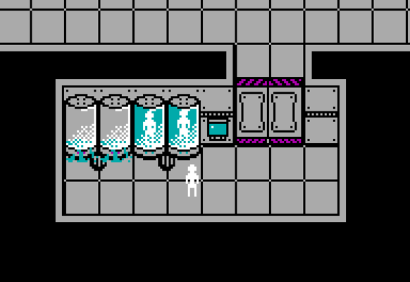
In Consignment, only north wall faces are visible
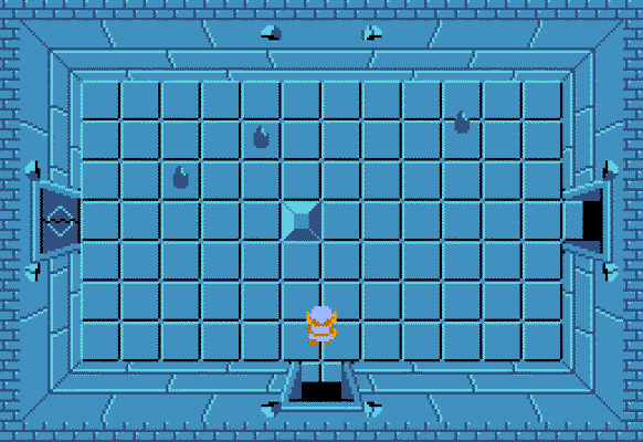
Games like the Legend of Zelda show all wall faces
Photo: https://www.zeldadungeon.net/
Audio
I don’t know much about audio and didn’t have time to record my own samples anyways so for the game’s sound effects, I used the FilmCow Royalty Free Sound Effects library. This library turned out to be the perfect fit as it had a ton of great ambient sounds as well as scifi effects.
I’ve always loved the computer voice lines from Prey 2017, such as those from Morgan’s Suit, so I wanted to give Sentinel a similar voice. I followed a tutorial for creating robot voices which got me pretty close but I wound up tweaking the steps a bit. For the final mix, each line was comprised of two tracks each with a copy of my voice but with different effects applied:
- For track 1:
- Increase pitch 10%
- Add echo with a delay time of 0.02 and decay factor of 0.6
- Decrease pitch 20%
- Decrease pitch 20% again (adjusting once by more didn’t get the same effect as doing it twice)
- For track 2:
- Reduce tempo 2%
- Add echo with a delay time of 0.01 and decay factor of 0.6
Something I found while mixing the audio was I needed to break lines up into shorter phrases. Applying a tempo adjustment to longer lines would cause the tracks to desync so much that you couldn’t make out what was being said. It also sounded odd during playtesting to have voice lines start with no introduction so I added a couple beep sounds from FilmCow’s library to the start of each line and adjusted their pitch to create an announcement chime.
Architecture
For being such a short game, Consignment has more structure than you might expect. The game is divided into two core scenes: main and ship. The main scene primarily handles switching screens, loading the ship scene, and spawning the player. Meanwhile, the ship scene is responsible for tracking game state. Nothing particularly noteworthy here; however, it’s the structure of the ship scene that I really want to discuss.
The ship scene is built very literally with it being comprised of several smaller scenes each representing one of the main locations from the game: the cryo room, the bridge, and engineering storage. Each of these room scenes has its own tilemap, audio queues, trigger volumes, and scripts. The ship scene itself only actually contains the hallway tilemaps and the logic to relay signals between the rooms.
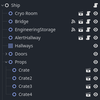
The tilemap, doors, and props in the ship scene are just for the connecting hallways
The idea was to make each room fully self-contained in code and layout. The rooms know nothing of each other nor do they know how the ship scene works. They just emit signals when something significant happens and expose public methods to change their state (if applicable). Picking up the override codes from engineering storage is a good example of this segregation of duties:
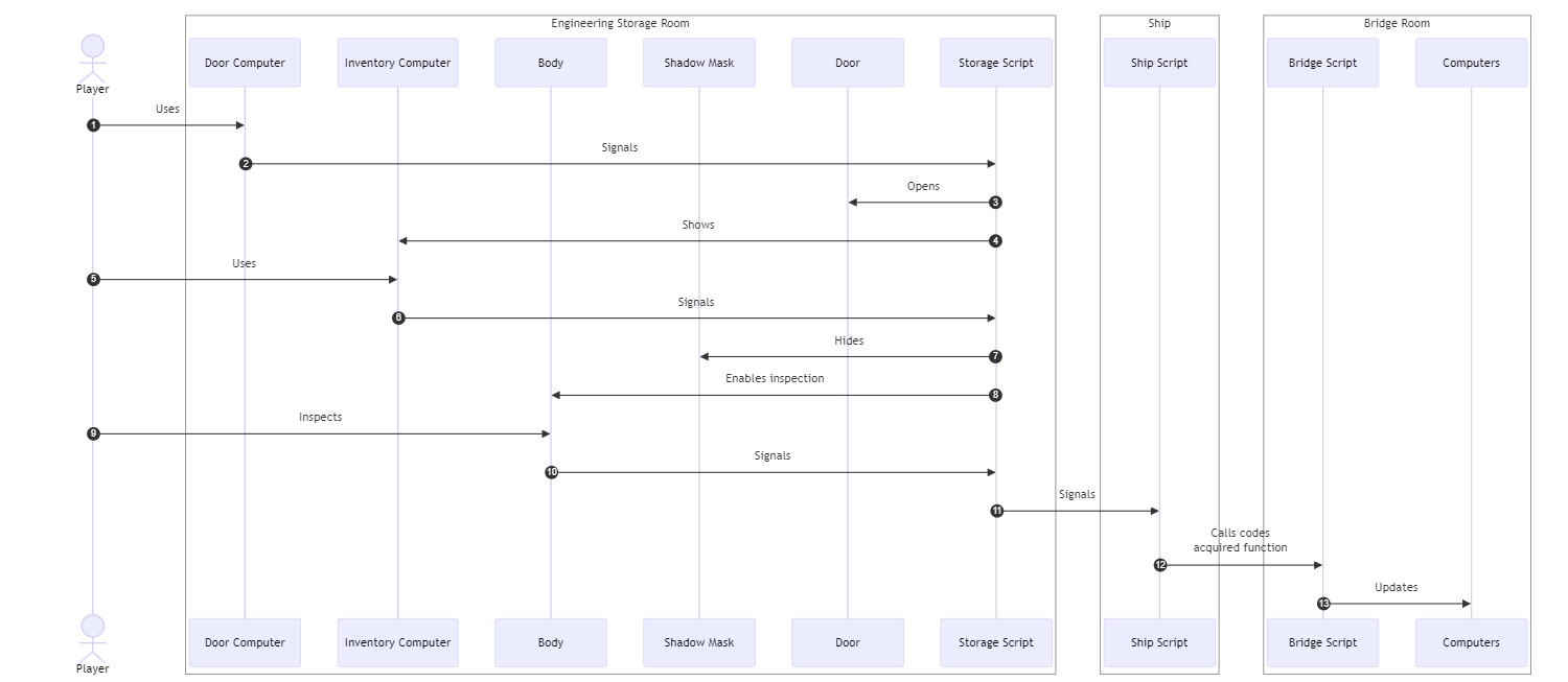
Here you can see the "signal up, call down" methodology the architecture is based around
Aside from keeping game logic separated, this approach also made it easy to adjust the ship’s layout. Just drag a room somewhere, update the hallway tilemap, and I’m done. This made development a breeze since I could quickly test with rooms close together.
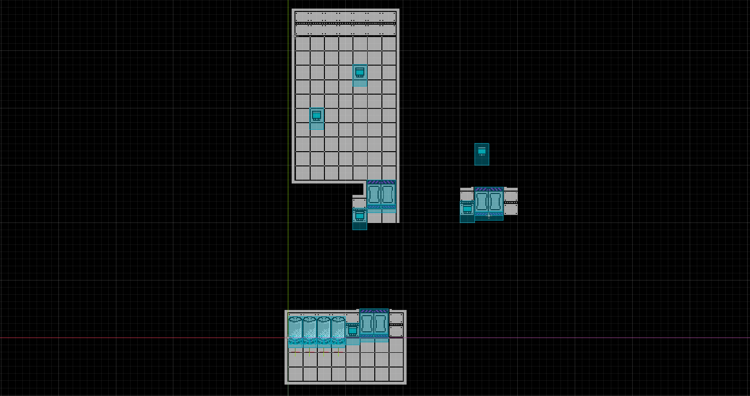
All of the rooms were next to each other for most of development
There are many different ways to structure a game with no one approach being right for every situation but this is certainly one I’ll remember for the future.
Reception
Of the 497 entries, Consignment placed:
- #13 in Story
- #22 in Sound Design
- #42 in Enjoyment
- #75 in Horror
- #83 in Aesthetics
And WOW! I’m honestly shocked by how well it did and super thankful to everyone who took the time to play and give feedback.
I didn’t expect rankings anywhere near this high but I have to admit enjoyment is the most surprising. Given my gameplay loop boils down to just pressing ‘E’ a few times, I expected to score much lower than I did. While games like SOMA and Amnesia also heavily rely on so-called fetch quests, they have additional mechanics to keep the game interesting along the way like stealth. I suspect that had Consignment been longer, I would have scored much lower but as-is I think the short duration helps keep the game from feeling too stale.
Aside from enjoyment, I was also surprised just how many people commented about liking the art direction. It was especially cool to see people mention it taking them back to their DOS gaming days. I may just revisit this palette again in the future because of that.
If you haven’t already, I highly recommend checking out the other great games submitted to this year’s Scream Jam. Some of my favorites are:
Retrospective
The ending
My intent was for the horror to come from the player’s realization of being in an unwinnable situation with others depending on them to do something about it. I wanted players to experience the dread and regret of letting someone down and to punctuate it with a feeling of isolation and lack of control. Unfortunately, I’m not sure those themes came across how I intended.
By far, the most common feedback I received was from players not sure if they had “failed” the game or not. It’s one thing if a player feels conflicted about what they did but it’s a whole other problem when they aren’t sure if they completed the game. Not knowing could have left some players believing there were other “better” endings they just didn’t find which takes away from the theme. In retrospect, I can definitely see a few reasons why players were led to think this way.
For starters, the power-rerouting segment at the end looks too much like it has multiple solutions. In reality, no combination of systems can supply enough power to restart the engines without also shutting down the radiation shields. I tried to make this obvious by showing how much power was required and how much was available on the main computer; however, I don’t think this was clear enough and I suspect most players didn’t even know the main computer would tell them that. This would have been much clearer if the rerouting took place through an interactive menu with a real-time power readout and switches to let them experiment.
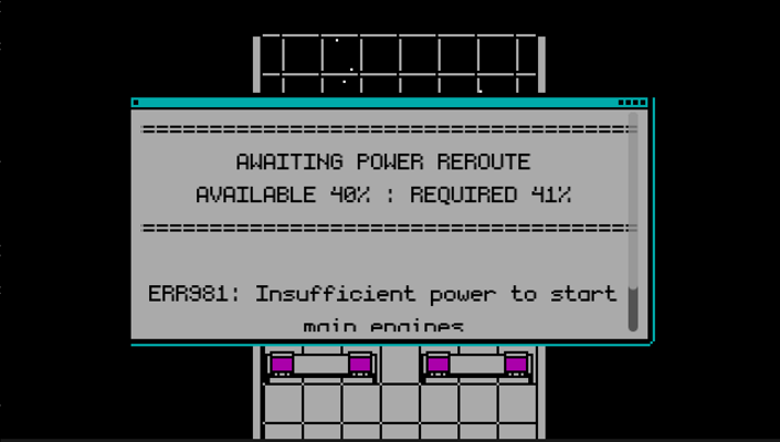
The result of re-routing power from every system except the shields
Furthermore, I don’t think the impact of turning off the radiation shields was very clear. I got the impression some players thought at least some of the crew/passengers survived. In hindsight, I had to lookup what a lethal dose of radiation was while writing so I shouldn’t have expected players to know just how deadly 8,000msv is. I tried to make this clear with the final message indicating “multiple cryotube failures” in the cargo hold but I don’t think it was enough. Forcing the player to reroute power from something more directly impactful like cryo storage may have been a better option. Alternatively, showing the immediate signs of radiation sickness on the player and other cryotubes may have also helped.
On a related note, I’m not certain I made it clear enough the ship was beyond hope of rescue by the end. Through the bridge computers, I was trying to convey how the ship had lost its communications array, most of its lights/beacons, only had a few days of oxygen left, and was 20 years away from anyone who could help it. Additionally, the ending sequence was meant to imply the ship’s reactor had melted-down and taken the hydraulics with it causing total power loss and sealed doors. Despite all this, I don’t think I did enough to build the world outside the ship to make it clear why nobody would be able to help.
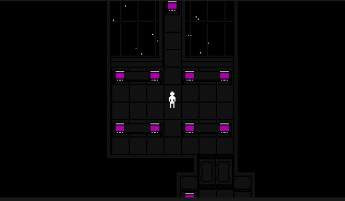
The final moments of the game before the credits were meant to let the player reflect on just how final the ending is
Audio design
Some great feedback I got on the submission was to look into applying ring modulation to the voice to make it sound more robotic. Audacity didn’t appear to have a ring modulation effect built-in but I found a plugin for it online. It’ll take some time to learn how best to use it but I definitely like the effect it creates.
Code
Changing the game’s premise after I already started development left the final build with quite a bit of dead code for handling the character transitions. In fact, there is even an entire character select menu and death system built in that just never gets activated. Despite that, the code was actually pretty clean up until the last two days of the jam.
Then all hell broke loose.
The main problem is with the segregation of duties between the ship and bridge scenes. See, the ship’s script is what triggers all the random ambient sounds and screen shaking effects while the bridge is what animates the ending sequence. This sounded fine when I first designed them except I forgot two things: 1) the ship needs to stop playing random sounds when the ending starts and 2) the ending animation requires screen shaking. I didn’t have time to refactor the scenes so the ship and bridge wound up coupled by a complex sequence of signals the bridge emits to request different sound and screen shake effects from the ship.
Actually, the ending sequence is even more rough than that. The sequence isn’t made using Godot’s AnimationPlayer like you might expect. It’s actually built from a ton of sequential timers. I knew Godot had an animation player; however, I didn’t know it could control scripts and I didn’t think I had enough time to learn about it anyways. Now that I’ve had a moment to read about it, I know it would have worked much better than what I did.
These are just a few of the callback functions for all the ending timers
Wrap up
Overall, this turned out to be a great way to finally learn Godot and get back into making games again. Even after the jam, I’ve been tinkering with small projects in Godot and wanting to learn more. I’m already excited for my next jam and looking to enter another this winter.
All that said, I haven’t been sleeping on my other projects either. I’ve been working to learn FreeCAD over the past few weeks with the intent of shifting my half-scale pinball machine development over to it.
Rivermod
Modding Riverworld | Rivermod
My history with Riverworld
Years ago, I picked-up a copy of Cryo Interactive’s 1998 RTS, Riverworld, from a bargain bin at Big Lots. It was my first exposure to the genre and one of the first 3D PC games I had ever played. I had no knowledge of the books it was based on but found myself immediately entranced by the game’s atmosphere.
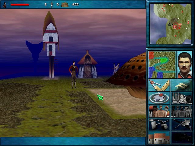
Riverworld creates one of the most unique atmosphere's I've seen in a game.
Unfortunately, I could never quite beat the game as a kid but I did find other ways to enjoy it. Being curious about how games worked, I tried poking around the game’s files and quickly realized I could edit textures and give myself unfair advantages in the levels. Eventually, I moved on to newer fancier games but I never forgot about Riverworld.
Fine, I’ll do it myself
Last year, I finally decided to pick up Riverworld and beat it. As I played the game again, I remembered the fun I had modding it as a kid but was surprised to find almost no resources about the game online. Having some reverse-engineering know-how, I decided then to start building my own modding tools.
Now, almost exactly one year later, the first release of the tool is ready. Rivermod v0.1.0 is freely available to download from my GitHub along with a wealth of research I’ve done into the game’s proprietary file types. It’s by no means done (the tool really only allows managing saves and viewing maps/models at this time) but there’s enough research available to customize levels, change enemy behaviors, and more.
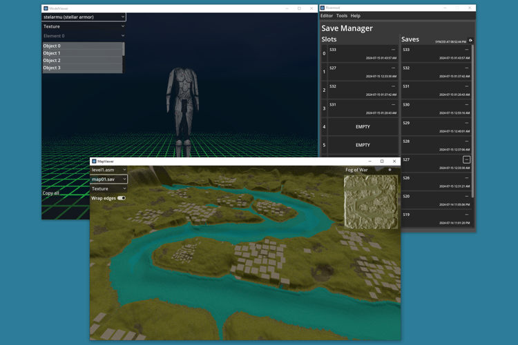
Rivermod's save manager, map viewer, and model viewer
Game preservation
Along with the modding tools, I’ve documented how to run the game on modern hardware and even tips for playing if you’re bad at RTS games (like me).
I’ve also contributed several high resolution scans of the game’s box, CD case inserts, and manual to archive.org to help preserve the game’s legacy.
What’s next
Rivermod is a project I’m very passionate about; however, I recognize that not many people will use it (if any) and because of that I can’t justify spending too much more time on it. Part of the reason it took so long to release was me wrestling with that fact.
Regardless, I do have designs to cleanup some of the project’s jank (don’t look at the map viewer or model viewer code unless you want to take psychic damage) and to enhance it with editing and export capabilities for the levels and maps respectively; however, this is a low priority for me since it is already possible to mod the game manually using the information I published to its wiki.
That’s where YOU come in.
Rivermod is completely open source and permissively licensed. If you’d like to dabble in the preservation of a game through modding, I’ll welcome any contributions to the code, file research, or UI/UX design.
Closing thoughts
Even if you don’t have an interest in modding, I’d still recommend everyone at least give this game a try. It’s not hard to find copies for cheap on Ebay and the game is genuinely unique for reasons I could yap about for hours. If nothing else, the box art will make one hell of a cool decoration.
Replacement Score Camwheels
How it all started
About a year ago, Joe’s Classic Video Games uploaded a video showcasing a cracked Chicago Coin score camwheel and their workaround to fix it. They mentioned how these camwheels crack over time and that nobody makes replacement parts for them. I didn’t think much about it at the time but more recently they uploaded another video talking about the same problem and how there are still no replacements. The workaround they used is relatively well known and does seem to hold up well, but this time I got to thinking how many machines have camwheels that are damaged beyond repair or have been salvaged from other machines over the years.
While I don’t own the vintage machines using these camwheels (or any for that matter), I do value preservation of old hardware and software so I decided to try and create models for these parts so others can maintain their machines. Actually, my original goal was to both re-create the original design as well as redesigning the camwheels to be more robust; although, I ultimately dropped the redesign efforts for reasons I’ll get into later.
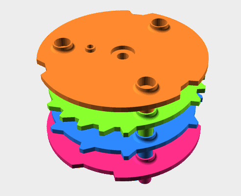
The completed cams. Those in the know may notice the cams are in the wrong order
Reverse engineering the dimensions
I checked online but unfortunately, nobody was selling any of the camwheels and without them it would be difficult to determine their correct dimensions. Thankfully though I was able to determine a few key dimensions from the videos I mentioned earlier. With those dimensions and a ton of screenshots from a number of different games, I went into image editing software to determine the remainder of the dimensions. It helped that Chicago Coin was a US company and appeared to primarily use fractions of inches for their dimensions making it easier to pinpoint the size from pictures.
I actually made a lot of good progress estimating the dimensions this way but there were a few I still wasn’t quite sure about. I could take a guess and release the models as-is but I wanted to be a little more sure before making them public. Thankfully, a Vintage Arcade Preservation Society (VAPS) and Pinside member, Deverezieaux, offered to help as they had already been using a 3D printed camwheel in their Sound Stage machine. The model Deverezieaux is using was created in conjunction with cerebral3d (ArtStation & Twitch) and with some luck they were able to find the old file and send it over. It’s a good thing they did too…
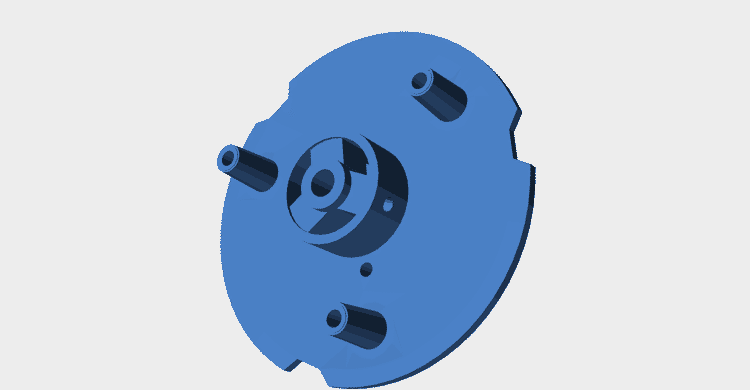
The camwheel model provided by Deverezieaux and cerebral3d
Their model confirmed a lot of assumptions I had made but it also confused me. The model had recesses I hadn’t seen in any pictures and it didn’t appear to match any of the known measurements I had found online. It was at this time I realized I made a mistake. I assumed all of Chicago Coin’s machines used the same camwheels since they all appeared similar but I now realized they changed the size of their camwheels at some point and my measurements were based on pictures from incompatible models.
Since I now had a known working model of the 190-517-X camwheel to reference, I decided it was best to put aside the dimensions I had been working on and instead focus on creating models for the 190-518-X, 190-548-X, and 190-620-X camwheels. I chose to make these specific models because I have seen from pictures online that they are the same size as the 190-517-X and I was able to find good technical drawings of their cam placements on IPDB.
Something’s still not quite right
As I was nearing completion of the camwheels, I realized something wasn’t quite right. The model I received from Deverezieaux had a recess in the back of the camwheel and a matching protrusion on each wheel’s shaft collar so I assumed these were meant to fit together; however, I noticed the protrusion on the shaft collar wouldn’t slot into the recess because the three support posts were the same length as the protrusion but did not have matching recesses.
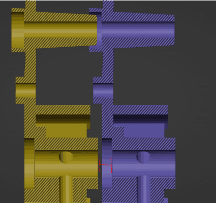
This X-Ray view of two original camwheel models showcases the problem. Notice how the support post is nearly flush with the next camwheel but the central support hasn't even reached its recess yet.
After confirming with Deverezieaux that the protrusion on the shaft collar was meant to fit into the back of the next I decided the best course of action would be to just add recesses for the support posts. Honestly, I’m not completely confident my approach is correct but without having an actual camwheel on hand to confirm I think this is the safest bet. Worst case scenario is someone does print a camwheel, finds out it’s not correct, and I update the CAD. It’s more inconvenient than anything else.
Data structures in OpenSCAD
I wanted to make the camwheels configurable but the software engineer in me didn’t like having tons of global variables or modules with 34+ parameters. When writing traditional code, I’d typically be inclined to create a configuration class to group large groups of parameters but OpenSCAD has no concept of classes; however, it does have lists.
With previous projects, I’ve tried creating rudimentary data structures to store my configuration values. My approach was to simply create a list and store each configuration value at a known index; although, I never really liked that model for a few reasons. Firstly, this approach is pain to add/remove parameters from as OpenSCAD doesn’t allow you to directly set the elements at an index. Related, you can only access the configuration objects by array index. Even if you do create wrapper functions to abstract the exact parameter index, you are still forced to manually update the indices in those wrappers to keep them in sync with the array.
// Create an LED specification using a helper function
LED_3MM = create_led_spec(
    body_diameter = 3,
    total_height = 5.3,
    base_diameter = 3.8,
    base_height = 0.81,
    lead_pitch = 2.54,
    lead_diameter = 0.5
);

// Helper function to create an LED specification list
function create_led_spec(
    body_diameter,
    total_height,
    base_diameter,
    base_height,
    lead_pitch,
    lead_diameter) = [
      body_diameter,
      total_height,
      base_diameter,
      base_height,
      lead_pitch,
      lead_diameter
    ];

// Abstractions to fetch various arguments from an LED specification list
function led_body_diameter(specification) = specification[0];
function led_total_height(specification) = specification[1];
function led_base_diameter(specification) = specification[2];
function led_base_height(specification) = specification[3];
function led_lead_pitch(specification) = specification[4];
function led_lead_diameter(specification) = specification[5];

// Module to create an LED from a specification
module led(specification) {
  body_diameter = led_body_diameter(specification);
  total_height = led_total_height(specification);
  base_diameter = led_base_diameter(specification);
  base_height = led_base_height(specification);
  lead_pitch = led_lead_pitch(specification);
  lead_diameter = led_lead_diameter(specification);

  body_radius = body_diameter / 2;
  base_radius = max((base_diameter / 2), body_radius);
  ...
}
Notice how any change to the create_led_spec function’s array will require changing the indices of the functions below it.
What I really wanted was something like a map/dictionary data structure where I could store key-value pairs but OpenSCAD doesn’t have anything like that… or does it? While it’s true OpenSCAD doesn’t have any map-like data structures, I learned it does include a nifty search function which can find the index of an element in a list. On the surface, this doesn’t seem like it would help until you realize that this function can also search nested lists. Thanks to dipi on StackOverflow for pointing this out detail.
With this, I could now store key-value pairs as lists inside a larger list then lookup those values by searching for the index of the element whose nested list contained the desired key. As an added bonus, having the parameter names in the specification list now also means that I can print the list to the console to see all of the named parameters when debugging.
// Helper functions to get any parameter's argument from a specification
function get_specification_parameter_index(specification, parameter_name) =
    search([parameter_name], specification)[0];
function get_spec_argument(specification, parameter_name) =
    specification[get_specification_parameter_index(specification, parameter_name)][1];

// The names of each parameter in the specification. I personally prefer functions over global
// variables.
function led_spec_body_diameter_parameter_name() = "body_diameter";
function led_spec_total_height() = "total_height";
function led_spec_base_diameter() = "base_diameter";
function led_spec_base_height() = "base_height";
function led_spec_lead_pitch() = "lead_pitch";
function led_spec_lead_diameter() = "lead_diameter";

// Helper function to create an LED specification
function create_score_camwheel_specification(
    body_diameter,
    total_height,
    base_diameter,
    base_height,
    lead_pitch,
    lead_diameter) = [
  [led_spec_body_diameter_parameter_name(), body_diameter],
  [led_spec_total_height(), total_height],
  [led_spec_base_diameter(), base_diameter],
  [led_spec_base_height(), base_height],
  [led_spec_lead_pitch(), lead_pitch],
  [led_spec_lead_diameter(), lead_diameter]
];

// Module to create an LED from a specification
module led(specification) {
  body_diameter = get_spec_argument(specification, led_spec_body_diameter_parameter_name());
  total_height = get_spec_argument(specification, led_spec_total_height());
  base_diameter = get_spec_argument(specification, led_spec_base_diameter());
  base_height = get_spec_argument(specification, led_spec_base_height());
  lead_pitch = get_spec_argument(specification, led_spec_lead_pitch());
  lead_diameter = get_spec_argument(specification, led_spec_lead_diameter());

  body_radius = body_diameter / 2;
  base_radius = max((base_diameter / 2), body_radius);
  ...
}
Is this approach way more verbose? Yes, absolutely. Is it easier to maintain? Also, yes. For simple examples like this, the extra overhead probably isn’t worth it but I really like the assurances it gives me when working on parts with many more options.
Enhanced camwheels
When I first set out on this project, I had the intent on redesigning the camwheels to be more robust. Why? Well there were two problems with the original design that I felt I could fix. Firstly, the shaft collar of the wheel is prone to cracking from its set screw being overly tightened into the aging plastic. Second, the cams will wear over time and eventually become too short to close the switches. I felt I could fix these issues by redesigning the camwheels to use a metal shaft collar and by having the main cams be machined from metal. Ultimately though, both enhancements were dropped.
For the shaft collar, my plan was to simply buy an off-the-shelf flanged shaft collar and attach it to the model. Unfortunately, I later discovered that while such shaft collars are readily available in any metric size, I couldn’t find any online retailer selling the imperial size required for the score motor’s shaft. I thought about just using the closest metric size but decided against it for fear of it creating too much wobble.
I knew there would be no off-the-shelf metal part suitable for the camwheel but I found it wouldn’t have been that expensive to get one custom made from an online machine shop (around $30 or so). I could have proceeded with this plan but I decided it wasn’t worth it after talking to Deverezieaux. You see, they had printed their replacement camwheel back in 2017 and reported it was still working fine so I figured a metal replacement just wouldn’t be worth the effort.
All that said, I did make one crucial enhancement to the original camwheel’s design. The original wheel has protrusions on both the top and bottom making it difficult to print without excessive support material. From what I could tell, the protrusions on the bottom weren’t actually needed so I included an option in the CAD to remove them thus making one side of the part flat and easier to print. Not the fanciest tweak but sometimes the simpler things are the most worthwhile.
Custom camwheels
From the start, I knew my camwheels wouldn’t be perfect given I didn’t have a reference so I wanted to make the CAD easily customizable for others could add in more accurate measures later. I had intended to just upload a SCAD file to Thingiverse so people could customize the models directly in their browser; although, I found the models simply had too many polygons for Thingiverse’s customizer plugin to handle.
I still wanted the models to be easy to customize without prior CAD knowledge so I put together a template file explaining what all the different parameters did and how to set them. I also added a model viewer scad file with customizer settings to view each model and adjust the level of detail.
You may be wondering why I didn’t just make all the model’s parameters adjustable in OpenSCAD’s customizer. I had wanted to do this but decided against it for two reasons:
- I wanted users to have control over the parameters of each cam on the wheel and customizer has no support for a variable number of parameters to support this.
- With the template file, users can choose whether to use inches or millimeters. Customizer options have no (easy) way of supporting different units of scale.
As I mentioned earlier, the camwheels I created only fit later Chicago Coin machines. I have other projects I want to get back to and don’t have time to finish determining the measurements for the older camwheels. Since the earlier camwheels seem to follow the same basic shape, my hope is that making the models easily customizable will allow others to continue where I left off and create custom wheels to match the older designs.
Where to get the files
With all that said and done, I’m happy to say the four camwheel models are complete and available for download at Printables. The CAD files are also available in GitHub. If you run into any compatibility issues with these models, please let me know by logging an issue to the GitHub repo.
LOD-ing in OpenSCAD
The burden of complex assemblies in OpenSCAD
Nothing quite kills a workflow like having to wait 3s for your rendering to update every time you want to pan the viewport around your work. OpenSCAD’s Boolean geometry functions are great for rapid prototyping; however, building complex assemblies without optimization will quickly sink the framerate and refresh time of the preview window.
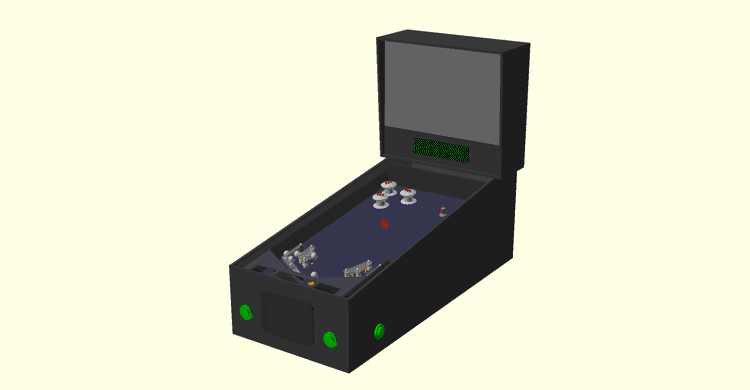
3 seconds wasn't an exaggeration. That's actually how long it takes to pan around my half-scale pinball assembly in the preview at full detail.
For especially complex models, each little detail is stealing away your precious performance. Chances are most details don’t even matter when you’re viewing the assembly as a whole; unfortunately, you can’t just outright remove the details because you do need them at some point.
OpenSCAD does provide a few built-in mechanisms to combat this problem and I’ll outline them below; however, I’ve found the built-in solutions aren’t always sufficient and have created one of my own I’d also like to share.
Reducing curve detail
OpenSCAD has no concept of true curves so the surfaces of circles, cylinders, and spheres are actually composed of many small straight line segments. As you add more “curved” surfaces to your model, the number of polygons being rendered increases dramatically; furthermore, Boolean operations performed on curved surfaces can really drag down performance due to the number of calculations involved. Thankfully, OpenSCAD does provide a mechanism to reduce the complexity of curves.
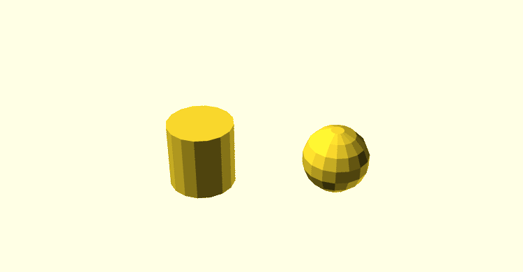
Examples of curved surfaces in OpenSCAD
The $fa, $fs, and $fn special variables control the number of line segments used to represent curves. The usage of these variables is a bit beyond the scope of this post but suffice to say $fa and $fs together provide granular control of curve detail while $fn can alternatively be used to control the detail but with much less granularity (and typically less performance gain).
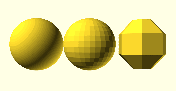
Examples of spheres with different $fa and $fs values. From left to right: 0.01/0.01, 1/1, 5/5
You can define the values of these special variables in code but I find it far more useful to define them globally and make use of OpenSCAD’s customizer feature so they can be tweaked in the editor.
/* [Preview Options] */

// The minimum angle of a curve fragments
$fa = 12; // [0.1:0.1:12]

// The minimum size of a curve fragment
$fs = 2; // [0.1:0.1:2]

sphere(d = 10);
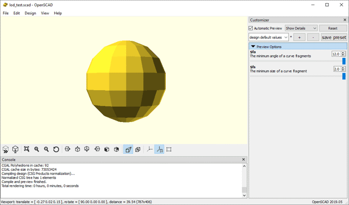
The result of the code snippet above
Overall, this approach works great for reducing the detail of models with many curved parts but it doesn’t help at all for other parts nor does it inherently allow for part-specific granularity.
Forced rendering
If you’ve ever worked with a complex part you’ve probably noticed that camera controls are much faster after rendering; however, rendering your entire scene after each change can take a while. In cases like these, OpenSCAD provides the render() module which allows you to force rendering of part of a model while still viewing the rest in preview mode. This comes with the tradeoff of increased preview refresh time but can greatly reduce slowdown of camera controls once refreshed.
translate([-10, 0, 0]) color("red") sphere(d = 10);
render() color("blue") sphere(d = 10);
translate([10, 0, 0]) color("green") render() sphere(d = 10);
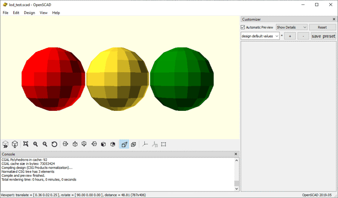
Notice how the middle sphere is yellow instead of blue but the green sphere is not. Any color applied before rendering will be reset but colors applied after will be preserved.
This technique is especially helpful in cases where you have one complex part that is reused multiple times in your assembly. Wrapping that part’s code in a render() module can greatly improve performance depending on how many copies are present. For example, the code below sees a 50% improvement in preview time when uncommenting the render lines but the improvement is negligible when there is only one copy of the complex part.
translate([10, 0, 0]) complex_part();
translate([0, 0, 0]) complex_part();
translate([-10, 0, 0]) complex_part();

module complex_part() {
  //render() {
    sphere(d = 10, $fa = 0.01, $fs = 0.01);
  //}
}
This technique can dramatically improve viewport responsiveness but it must be used sparingly to not significantly hurt refresh times. Wouldn’t it be great if there was a general-purpose solution to reduce the complexity of parts but without hurting the loading time?
LOD-ing
Many games and 3D applications utilize one or more “LOD”-ing techniques to improve performance of real-time rendering. The term LOD simply refers to any technique to dynamically change the level of detail in a 3D scene. Many implementations exist for this purpose but one of the most common is to simply replace complex models with lower detail variants when the user would not notice the difference. For example, many games may swap character models out for versions with fewer polygons when far from the camera as the details afforded by the extra geometry can’t be seen at that distance anyways.
OpenSCAD doesn’t inherently provide a LOD-ing mechanism but it’s easy to implement your own through the use of custom operator modules:
function min_lod() = 0;
function max_lod() = 1;

function clamp(value, min, max) = min(max(value, min), max);
function in_closed_range(value, min, max) = value >= min && value <= max;

module with_lod(lod) {
  $lod = lod;

  children();
}

module when_lod(min, max = max_lod()) {
  effective_level_of_detail = is_undef($lod) ? max_lod() : $lod;
  clamped_min = clamp(min, min_lod(), max_lod());
  clamped_max = clamp(max, clamped_min, max_lod());

  if (in_closed_range(effective_level_of_detail, clamped_min, clamped_max)) {
    children();
  }
}
There’s a bit to take in here so let’s break it down one step at a time.
- In my implementation, the desired level of detail for a part is given as a fraction between 0 and 1 with 0 being least detail and 1 being the most (aka the LOD level). The
min_lod()andmax_lod()functions simply define this range. - The
clamp(value, min, max)helper function limits the providedvalueto a number betweenminandmax(inclusive). - Similarly, the
in_closed_range(value, min, max)function returns true only whenvalueis betweenminandmax(inclusive). - The
with_lod(lod)module sets the fractional LOD all child objects shall be rendered with.- The special variable
$lodis set so that all child objects inherit the current LOD level without needing parameters for it.
- The special variable
when_lod(min, max)acts as a conditional block which only renders its children when the current LOD level is between the provided min and max.- If
$lodhas been defined by a call towith_lod(lod)then we fetch its value; otherwise, we assume the maximum LOD level is desired. - We next perform some input sanitization to ensure the provided minimum LOD level value is between 0 and 1 and that the maximum LOD level is between the minimum and 1.
- Finally, we only render our child objects if the current LOD level is between the desired minimum and maximum.
- If
Using these modules, I can choose which details are hidden at different LOD levels or even replace an entire component with a lower-poly version. For example, the following module defines a solenoid assembly whose frame is replaced with a plain cube at lower LOD levels:
module t_tulead_solenoid_add06190484(stroke = 0, plunger_angle = 0) {
  // ...

  when_lod(min = 0.75) {
    t_tulead_solenoid_add06190484_frame();
    translate([0, 0, -body_length + wall_thickness]) {
      t_tulead_solenoid_add06190484_coil();
    }
  }

  when_lod(min = 0, max = 0.75) {
    t_tulead_solenoid_add06190484_simplified_frame();
  }

  rotate([0, 0, plunger_angle]) {
    translate([0, 0, plunger_position]) {
      t_tulead_solenoid_add06190484_plunger_assembly();
    }
  }
}
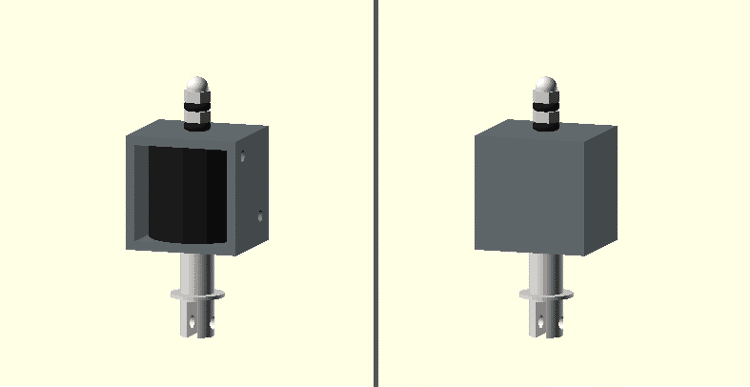
left: the max detail of the model, right: the same model with a lower LoD
While it may not seem like a major difference now, removing a few extra details here and there can have a big impact of preview performance especially for frequently used parts.
Mapping the Ishimura
What’s an Ishimura and why am I mapping it?
A few years ago, I decided I wanted to build a 1:1 replica of the USG Ishimura, a fictional deep space mining ship from the Dead Space video game franchise, in another game called Space Engineers. For the uninitiated, Space Engineers doesn’t really have an end-goal other than building, programming, and inevitably crashing large space ships for the heck of it.
A shot of the Ishimura from one of the game's cutscenes
Given the Ishimura’s immense size (over 1.6km long according to the game’s art) and Space Engineer’s performance issues with large ships, I didn’t really expect a replica of the Ishimura to be usable once created. That said, I still liked the idea of piecing together the various details about the ship we see it throughout the games.
I managed to build out a few notable sections of the ship (screenshots at the end of this post if you’re interested) but the project eventually shifted to just mapping the Ishimura’s interior and exterior without Space Engineers as reconciling the details across each game become a project of its own. Ultimately, I put this effort on hold for a couple years but I wanted to share some of the challenges I faced and where I plan on taking this project in the future.
Fair warning, the rest of this post is going to be me overanalyzing and speculating about inconsequential design details of a fictional space ship from a game released over a decade ago. If that doesn’t exciting, I don’t think the rest of this post will change your mind. With that out of the way, let the rambling commence.
Why do I need to map anything?
I had originally planned on exporting the 3D models directly from the Dead Space games and using those as a reference but discovered nobody had found a way to do so even a decade after the game’s release (and that’s not for a lack of trying). While some of the game’s characters and animations were exported, the level geometry is encoded in a format nobody has been able to decode to this date.
Without the game’s 3D models as a reference, I begrudgingly captured literally thousands of reference screenshots and dozens of hours of video across each of the games and movie (the second movie didn’t happen and if we all believe that hard enough we may yet will it out of existence). You might think I’m exaggerating but I assure you I’m unfortunately not. To date, I have over 1500 screenshots for Dead Space 1 (DS1), nearly 500 for Dead Space 2 (DS2), and a few hundred from Dead Space Extraction (DSE) and Dead Space Downfall (DSD).
With all those references, you might think recreating the Ishimura would be easy but there’s still a fundamental problem with using references from the games. Fact is, the levels of most video games rarely fit together if you try to combine them. For example, it’s not at all uncommon for the insides of buildings to be larger than the exteriors or for doors to be placed in locations where there couldn’t possibly be anything behind them and that’s just within the same game. It’s even rarer for the same locations to be consistent across multiple games.
Just to be clear, in no way do I mean this as a dig at game developers. The reality is most players would never notice these inconsistencies so it’s not a good use of a developer’s time to agonize over details like these. It’s far more important that the game be fun and Dead Space most certainly is. Unfortunately for me, I do need to care about these details to build a complete map and there are a lot that need reconciling.
The challenge
To give an example of the inconsistencies I found in the Ishimura’s design, let’s examine one the Ishimura’s most iconic details: the sets of gigantic ribs surrounding much of the ship. Every depiction of the Ishimura has these ribs but exactly how many does it have? The answer depends on where you look. Just take a look at the following screenshots:
Dead Space 1 - The player's first glimpse of the Ishimura - 8 pairs of ribs
Dead Space 1 - A logo of the Ishimura seen throughout the ship - 9 pairs of ribs
Dead Space Extraction - The exterior of the Ishimura - 7 (or possibly 6) pairs of ribs
These are only a few of the screenshots contributing to this conundrum and only one of many, many inconsistencies to reconcile. Just for fun, here’s a few more in rapid-fire fashion:
- The main tram tunnel in DS1 is wider at the hangar bay than it is at other stations despite the tunnel width being constant in DS2.
- The view from the breached wall of the medical deck is of the Ishimura’s left hull but placement of the deck’s tram station implies the deck is actually on the right and much further back.
- DS1’s hangar bay tram station has a door half-way up the wall of the tram tunnel (near the control room) seemingly for unloading cargo but is several meters away from the tram with no obvious platform to reach it. The game’s kinesis modules could explain the gap but the tram still doesn’t have anywhere to store cargo.
- DSE shows a drain tunnel directly beneath the main tram line but later shows a small cargo gondola that appears to occupy that same space.
- The hull of the Ishimura appears white in DS1 and DSE when performing a space walk but the exterior is depicted as copper or bronze in every other circumstance.
- Shots of the Ishimura’s underside show a single large circular opening which is likely the centrifuge; however, there should also be at least one more square opening for the mining deck.
- Posters in DS1 depict the tram system as being a loop; however, DS2 shows the system is not and DS1’s first chapter also heavily implies it’s not as a single broken car is enough to block the entire line.
- There is no opening in the tram repair bay for the tram hanging in the repair bay to have gotten there.
- Unless the Ishimura is much wider than depicted, the communications array would be sticking noticeably far out the side of the bridge.
- The section of hull beneath the bridge’s ADS cannon should be visible from the bridge’s main deck according to the in-game map but it isn’t.
- The mining deck in DS1 is pointing down at the planet but it should be tangent to the planet given its floor is parallel to the rest of the Ishimura which is definitely tangent to the planet.
- Parts of the in-game map of the refueling bay in DS1 are backwards from the actual layout of the level.
- The Ishimura’s hangar bay is backwards in DS2.
- The games establish that gravity tethers always form a beam from the source to their target but we never see such a beam for the gravity tether that damaged the USG Kellion.
- Dead Space Downfall refers to the main hangar bay as bay 17 while Dead Space Extraction refers to a smaller hangar as 47. If hangar bays are numbered sequentially, the Ishimura would have more hangar bays than it physically has room for even if we assume all of the unseen bays are of the smaller size.
- The main hangar bay in Dead Space Downfall is missing its two elevated walkways, the control tower, and the gravity control station.
- The gravity tunnel carrying rocks through the mining deck doesn’t line up from room-to-room.
It’s not all negative
I wasn’t surprised to see inconsistencies in the games’ level design but I was surprised at just how many design details are consistent across the franchise. For example, the Ishimura’s runway is depicted almost identically between Dead Space 1 and Dead Space Downfall. Similarly, there are several permanently locked doors in Dead Space 1 that we actually get to see behind in Dead Space Extraction.
Even beyond direct design details, the games also give hints at what other aspects of the Ishimura’s design may be used for. For example, the hangar bay in Dead Space 1 features four large doors on the walls of the bay. We see behind one of the doors later in DS1 and learn that it contains a cargo elevator down to the ship’s cargo bay; however, it also contains another identical locked door that we never get to see behind. Late into Dead Space 2, we revisit the Ishimura and upon close inspection we see that we are actually entering the ship through a different pair of those locked doors in the hangar bay. This heavily implies those doors are actually an airlock to the ship’s exterior which would make a great deal of sense seeing as how they also have direct access to the cargo bay making for easy loading/unloading.
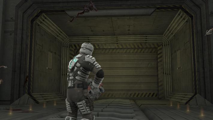
The open cargo door in the hangar bay of Dead Space 1
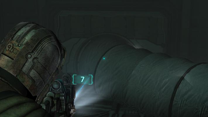
The cargo door Isaac enters the Ishimura through in Dead Space 2
I could go on about other interesting details I noticed when comparing the games but I’ll save that for another time when I have those portions of the ship mapped out.
Where to go from here
Ultimately, my goal is to create a detailed 3D schematic for the entire Ishimura inside and out. In this schematic, I want to incorporate all the locations seen in Dead Space 1, 2, Extraction, and Downfall while also filling in areas of the ship we never see with reasonable speculation. I may decide to include details from the upcoming remake of Dead Space 1 as well but that will depend on how faithful it is to the original.
Thus far, I’ve reconciled some of the ship’s main locations in notes but I haven’t started modelling anything yet. Part of the reason for this is I still don’t have a way of measuring features of the ship. I’ve considered estimating Isaac’s height and using him as a reference but being even a few mm off here and there in a ship this large would quickly accumulate too much error in the design.
Something I’m considering is using a process monitor to find the player’s coordinates in running memory and using them to at least measure the relative sizes of each room. Failing that, I’m also curious if a simultaneous localization and mapping (SLAM) algorithm could be used to build a map of a level based on video input. Regardless of the approach, I have to find some solution to this problem as it’s the main reason I put this project on hold.
I also need to decide what software to create the schematic in. Unsurprisingly, real industrial schematic software is far more complicated than I want to deal with; however, I also don’t want to just create a 3D model of the Ishimura as it would be far too complex to view.
If you have some ideas or want to help out with the project, feel free to reach out via discussions or Twitter.
Space Engineers Replica Screenshots
I want to leave you with a few screenshots taken from my last attempt at replicating the Ishimura in Space Engineers. None of these sections are final as I planned on creating mods to more closely match the Ishimura’s architecture but I still think they look pretty good as-is.
A side view of the replica. The thin scaffolding represents the full size of the ship. To give an idea of scale, the small box just behind the rib is the entire hangar bay from the next screenshot.
A view from the floor of the hangar bay. There is no working bay door at this point but I did add the forcefield seen near the end of the first game.
The Ishimura's flight lounge with the quarantine alarm active
The hangar bay tram station and a view of the tram control room across the tunnel
The Ishimura's runway and part of a conning tower as depicted from the intro to Dead Space 1 and the crash scene from Dead Space Extraction