Speaker Panel | Half Scale Pinball
Projects:
Sight and sound
I’ve made a lot of small updates to the pinball machine since my last post but let me first introduce the new speaker panel I’ve designed.
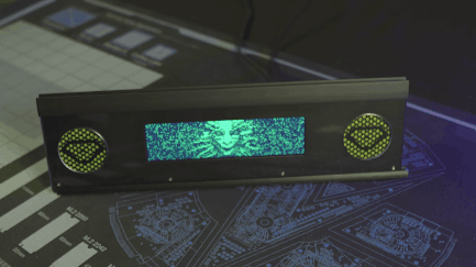
The bolts at the bottom won't be visible once the artwork is applied to the acrylic cover
The panel houses the 1920x480 display I mentioned in my DMD post as well as two 2" speakers embellished with green mesh and TriOptimum logos.
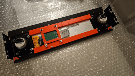
The panel secures into the cabinet with M4 studs and thumb-nuts allowing for easy removal
As an aside, if you’ve only played the System Shock Remake or System Shock 2, the TriOptimum logo may look a bit wrong to you; however, that actually is how it looked in the original game. Interestingly, you can find media released with the original game that does show the more modern logo but I chose to use what you actually see while playing.
The original logo from one of the game's cutscenes
Panel design
One of the reasons it’s taken so long to get a new post out is that I’ve been working to convert the project from OpenSCAD to FreeCAD for added features. Some of these features, like support for sheet metal bends, were essential to making progress on the speaker panel; however, in FreeCAD, nothing is easy.
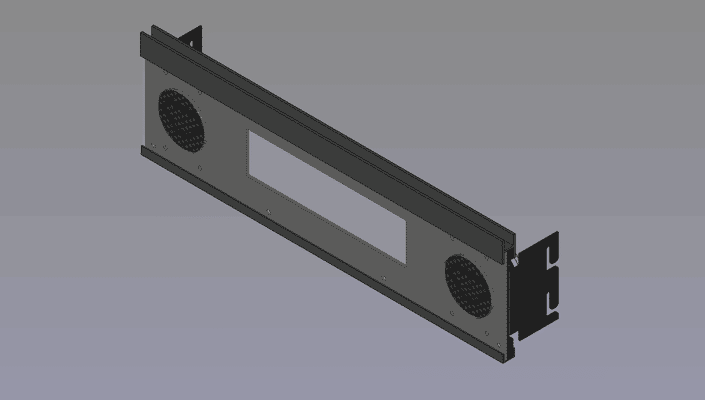
The finished CAD model of the speaker panel
One of the main challenges I faced was just trying to figure out how to make a hexagonal grill for the speakers with the TriOptimum logo overlaid. In OpenSCAD, I’d just use for-loops and the difference operation to “cut” the hexagons out of panel’s profile and the union operation to add back the logo but it’s not that simple in FreeCAD.
The problem I ran into is that FreeCAD’s sketch workbench doesn’t appear to have any way of creating a repeating pattern. Manually sketching each grill hole would take forever and bog down the program so I had to find another solution. Thankfully, someone else already made a tutorial for creating grills in FreeCAD. I had to deviate some to get the results I needed but ultimately, the process boiled-down to the following:
FreeCAD grill tutorial
Disclaimer
I’ve read it’s not good to mix the PartDesign and Part workbenches but this is the only way I knew how to do this and it hasn’t broken on me yet.- Create a master sketch of the speaker panel with all the mounting holes and DMD cutout but no speaker holes
- Create a master sketch of a single grill hole (a hexagon in my case)
- Create a master sketch of the TriOptimum logo I wanted over the grill
- Add dimensions to a master spreadsheet defining width and height of the hole grid as well as how many holes should be present horizontally and vertically
- Create a grill “punch” file which will serve as a virtual hole punch for making the grill
- Create a PartDesign body for the grill grid
- Add a backing-plate which all the hexagons will attach to (since a PartDesign body doesn’t allow disconnected geometry)
- Extrude a single hexagon from the plate near the corner
- Use the MultiTransform operation to first repeat that hexagon into a line across the plate and then again to repeat that line into a grid using the dimensions from the spreadsheet to define the length and occurrences of each pattern (all extrusions must touch the plate or the operation will fail)
- Create a second PartDesign body which will serve as a mask to remove parts of the grid where the logo will be
- Create a backing-plate (again just to ensure all parts of the logo will be connected)
- Extrude a cylinder from the backing-plate the diameter you want the speaker hole to be
- Pocket the logo from the cylinder such that areas you want the logo to show are not solid but do not allow the pocket to go all the way through the plate or the operation may fail if the logo has disconnected geometry
- Create a new Part body and move both PartDesign bodies into it
- Perform an intersection of the bodies so that you’re left with the “punch” for the grill
- Remove any shapes from the punch that would produce holes too small for your fabricator to cut by applying a CompoundFilter and setting the Window To value to a number high enough to remove the excessively small shapes
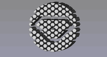
The "punch" for the speaker grills
- Create a PartDesign body for the grill grid
- Create a panel file for the final part
- Add a PartDesign body
- Extrude the speaker panel sketch to whatever thickness your material is
- Add a Part body and move the PartDesign body under it
- Link the punch file and move it to left speaker position; repeat for the right
- Apply a cut operation on the Part body using the left and right punch bodies
- Export the final Part body as a DXF to get the final cutting profile
Yeah… it’s a complicated mess that would have taken a fraction of the time to design in OpenSCAD but to be fair there are many other parts in this design that would be a nightmare to make in OpenSCAD.
Speakers
Given the size of the display, I only had room for ~2" (50mm) front speakers. That’s not a lot of room to work with but thankfully 2" speakers are a common standard so there’s plenty to choose from. I don’t know much (or anything) about audio but I do like how my Logitech X-140’s reproduce System Shock’s soundtrack so I looked for speakers that sounded similar.
As is a theme for my harebrained schemes, I found some really cheap speakers on Amazon and figured I’d give those a test first. I’ve heard it’s pretty common for a lot of higher priced speakers to actually be poor quality so I figured I’d start from the lowest possible price and work my way up instead of overpaying from the start.
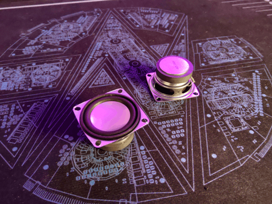
At only $4 each, these are surprisingly not terrible
And honestly… I didn’t think they sounded that bad… or at least not when I had them on my desk. They had absolutely no bass at first when I had them propped up on their boxes but sitting them on my desk greatly improved their sound. Thing is though, I know mounting them in the backbox would help but I don’t think it would have quite the same effect as sitting them on a wooden desk. I assumed I’d need speakers that had more bass on their own if I wanted them to sound good.
I should mention at this stage I was determined not to buy a dedicated subwoofer for a few reasons:
- I couldn’t find a subwoofer small enough to fit under the playfield (even 6" subs are quite tall)
- My cabinet isn’t meant to have legs so even if I could mount it in the bottom, it would be pressed against the table
- The cheap amp I bought to test with was only 2 channel
Anways, based on some reviews I decided to order two different speakers from Dayton Audio in the hopes that one would have better bass: the PC68-4 and the DMA58-4. Both models sounded very similar to me but I felt the DMA58-4 was slightly closer to what I wanted; however, neither solved the bass issue.
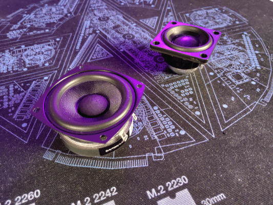
The PC68-4 (left) and the DMA58-4 (right)
It might be possible to get small speakers with good bass but I decided to go ahead and get the smallest subwoofer I could find along with a better amp. Unsurprisingly, this greatly improved the sound. Even the original cheap speakers sounded much better with the sub; however, I decided to stick with the DMA58-4s.
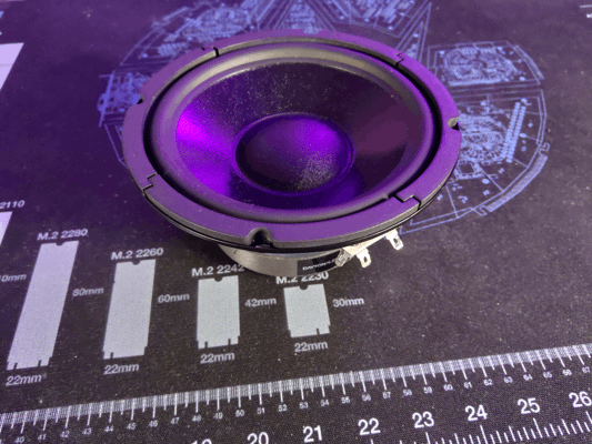
The sub may look small on camera but it's going to be a challenge to fit into such a small cabinet
Having good audio is great and all but it won’t do me any good if I can’t fit the speakers in the machine. Like I mentioned earlier, I can’t really put the sub in the bottom like a full size machine since it would interfere with mechs on the bottom of the playfield.
I don't have any mechs in the center of the playfield yet but if I did the speaker would interfere
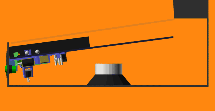
Mounting the sub in the back clears the playfield; although, I may regret this later when I need to install the power supplies. I’m hoping the sub will sound okay in the back.

The sub's magnet is pretty close to the back of the playfield so I may need to move it down some to not pull the ball
New test stand
The last test stand I designed worked but I had some issues with it:
- The playfield kept falling out when I moved the stand
- There wasn’t anywhere to mount the backbox electronics
- The front extrusions weren’t held on very well
- It wasn’t easy to adjust its width
- Overall it just felt flimsy
Using most of the same parts and some new brackets, I rebuilt the stand into something much more workable. The new stand is more rigid and adds hooks to the playfield so it can’t fall out anymore. The new design also gives me extra room at the back to mount electronics and room at the top for the DMD.
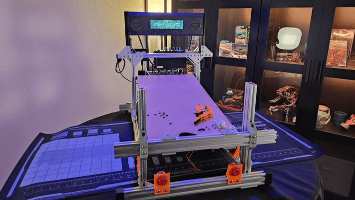
I'm confident this thing has more bolts in it than the average fighter jet
Intro animation
The fancy new speaker panel wouldn’t do me much good without something to display on it which is why I’ve been practicing my pixel art and working to reimagine the game’s intro cutscene as a DMD animation.
It’s still a work in progress but the idea is to have SHODAN’s into speech play while alternating between sequences like this and the high-scores.
Text-to-speech
If you’ve ever played the original System Shock then you’ll know SHODAN isn’t the only voice of Citadel station. There is a second artificial male voice used for things like countdowns and the reactivation of medical chambers. This second voice, commonly called the Citadel PA, is very clearly computer generated.
Why does this matter? Well while I do plan on using voice lines from SHODAN as callouts, the selection of lines is fairly limited and recording new lines in her iconic style would be difficult. That’s why I want to determine how the PA’s voice was made so I can recreate it for most pinball-specific lines.
To start, I listened to every interview I could find with the game’s composer, Greg LoPiccolo, for any clues on the voice’s design. Greg stated that he used SoundDesigner on a Mac to edit the audio and noted that it was very limited having no DSP effects and only being capable of cutting, pasting, EQ adjustments, and pitch shifting. Unfortunately, Greg never specifically mentions what speech synthesizer he used for the PA voice throughout any of the interviews I found ([1], [2], [3], [4], [5]) but this was a good start.
Given Greg had very limited editing capabilities at the time, I’m assuming he used the output of the speech synthesizer mostly as-is which should make it easier to narrow down. I started looking into which synthesizers were available before 1995 since the CD release of the game (the version with voice lines) released December 1994. So far, I’ve found the following:
- SAM - 1982
- DECtalk - 1984
- MacinTalk - 1984
- Dr. Sbaitso - 1991
- MacinTalk 2 - 1994
MacinTalk 3
MacinTalk 3 appears in many searches as being far more capable than its predecessors but what little information I can find seems to indicate it didn’t release until 1995. While it’s not unheard of for a game studio to have early hardware/software access to incentivize making games for a platform, I’m not convinced that would include something like an unreleased version of MacinTalk.I took an example line from the game and tried to reproduce it using emulators for each of the synthesizers. Below are the best examples I could come up with for now:
Based on this test, I’m fairly certain that DecTalk was the synthesizer used. The pronunciation, inflection, and speed match the original line far closer than others. That said, you may have noticed that I was being very specific about the version of DecTalk I tested and there’s good reason for that. I’ve found each version of DecTalk sounds very different; additionally, some of the settings that work in one build just sound like noise in others. Just listen to the default 4.61 and 4.62 samples back-to-back and you’ll hear a difference. Unfortunately, I can’t find any other versions of DecTalk to test with so 4.61 build 109 is the closest I have.
DecTalk has tons of settings and I haven’t really even begun trying to adjust the pitch or EQ of its samples so I still have a long way to go before I can replicate the PA voice. Despite the effort required, I’m confident I’ll get a better result from this approach than trying to train an AI text-to-speech model on what few PA lines there are; although, I have considered using machine learning to try and find the optimal combination of DecTalk, EQ, and pitch settings but for now that seems like it will take more effort than it’s worth.
Other updates
Pushing buttons
Something I forgot to mention in the last post were the flipper buttons I’m using. While these look like standard arcade buttons they’re much cooler. Pinball machines typically use leaf switches which have a smooth actuation while most arcade switches use clicky microswitches; unfortunately, the switches made for pinball typically have a large leaf switch attached to the back that takes up too much space and I don’t like clicky arcade switches.
The switches I’m using are special though. They look like arcade switches but they actually contain an integrated leaf switch. This makes them compact without compromising the switch feel. I got these at Ultimarc but they may be carried elsewhere.
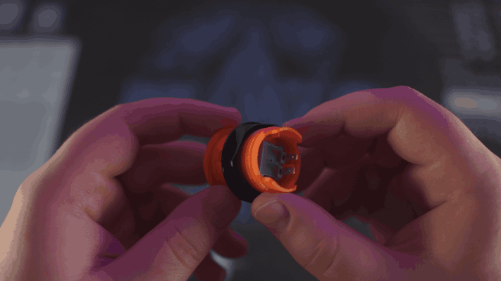
Here you can see the terminals of the integrated leaf switch
I haven’t decided the final switch color for the machine so I bought a pair of every color offered.
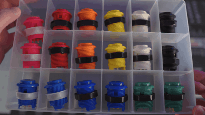
Some of these colors are giving me ideas for future machines
Polycarbonate
I mentioned back in my post about slingshots, that I intended to cover my playfield with a thin layer of polycarbonate to cover the holes for the inductive probes. Without the polycarbonate, the ball would skip over these holes so I needed to get some for playtesting.
Now unfortunately, I don’t have the tools (or the room for the tools) to make precision cuts in polycarbonate and I couldn’t find any company willing to machine it either. Companies like SendCutSend will machine thicker plates no problem but nobody appears to offer the thinner sheets I need. I figured my best bet for getting accurate cuts in the poly was to get a template made from a different material and use a plunge router to trace it into the poly. That said, I didn’t want to invest in a template at this stage so I decided to just order some precut poly from Amazon that happened to match the dimensions of the playfield and make the rest of the cuts by hand.
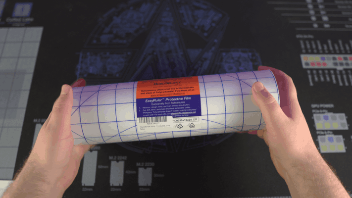
The 12"x24" roll of polycarbonate I found on Amazon
That was a mistake. The poly I got from Amazon shipped rolled and refused to lay flat even after being left under a weight for a week. I’ve never had to flatten poly before but the resources I initially found said the best approach is to sandwich it between two plates of glass and apply light heat for a short period. I had a feeling this wouldn’t end well but I was curious so I decided to order a couple cheap glass plates and a heated mat to test it out.
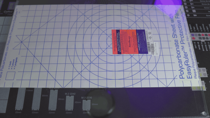
The polycarbonate between two glass plates
Why a heated mat? Well, I figured it would provide fairly even heating and be easier to keep at the target temperature. In a shock to no one, I cheaped out and the mat I got could only just barely reach 97F. I even tried insulating it from the air with a thick towel but the highest temperature I could get was 102F. With this low temperature, the poly was getting warm but it just wasn’t enough to do anything.
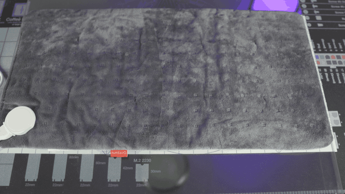
It's hard to describe just how sketchy this heating mat feels in person
At this point, I decided to go for broke and got out the hot air gun. Well, I actually tried using a hair dryer at first but it was too smart for its own good and refused to heat up the polycarbonate at close range. My sketchy hot air gun had no such issues though.
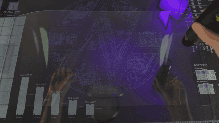
You can see just how warped the poly was with the top sheet of glass off
Despite my hot air gun being able to melt low temp solder, it still couldn’t heat the poly enough to relax it. I could get sections to lay somewhat flat if I applied heat for several seconds in one spot but it wouldn’t stay down even if I quickly pressed it between the glass and allowed it to cool under pressure.
I’m really not sure why this didn’t work. Honestly, I was surprised applying direct heat with the hot air gun didn’t outright melt the plastic (I was nearly touching the tip of the gun to the plastic most of the time). All I can think is maybe the plastic and the glass were just too much for the little gun to saturate.
At any rate, I decided to move on and just order poly from a different supplier. The new sheets came from TAP Plastics and while they did arrive rolled, they did lay mostly flat after leaving them sandwiched between the glass for a few days. Turns out buying supplies from reputable places saves time. Imagine that.
All that said, I don’t think I’m going to use the poly after all. In the FAST Pinball Slack group, some people brought up how polycarbonate sheets will actually expand with heat from the machine and cause the surface to warp. I’m also still not confident in my ability to cut the precise holes I need plus I may have found a better solution to my slingshots.
“Micro” switches
I was randomly searching Amazon, as you do, and came across something I’ve never seen before. Extremely tiny leaf switches.
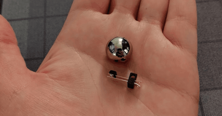
5/8" pinball for scale
Size isn’t everything though. What really matters is actuation force as the mini pinballs don’t even weigh enough to actuate a keyboard switch. And…
They’re perfect!
These little switches are easily actuated by the weight of the ball and even seem to resist vibration. I have no idea what these switches were designed for but I found even more variants of them on AliExpress and eBay with different mounting hole orientations. With these new switches, I’m re-evaluating the design of the slingshots and rollovers to use these instead. If I can get rid of the inductive probes, that would completely negate the need for a polycarbonate layer over the playfield.
Flipper redesign
Speaking of redesigns, one of the main reasons I switched to FreeCAD was to make designing the new flipper mech easier and I cannot stress just how much it’s helped. I haven’t quite landed on a final design just yet but I do have a couple interesting prototypes.
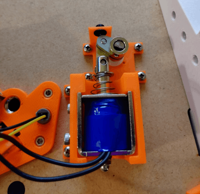
The first of the prototypes printed and installed
There’re a few big changes with this new design. For starters, the entire linkage is metal with stainless steel crank arms and a brass link. Less obvious is the custom machined rotary shaft with flats to drive to the flipper and crank arm. I’ve also switched to a much smaller solenoid and added a rubber backstop.
That’s sort of where the good things end with this design though. I chose to use a flat to connect the crank arm and shaft despite knowing that full-sized machines just clamped onto a round shaft to allow for adjustment. Suffice to say, I needed that adjustment. I’ve found that even slight variations in placement and spring tension result in the flipper bat being misaligned with the return lane. In this prototype, there is no way to adjust the resting position of the bat aside from cutting a new crank arm.
Furthermore, I want to switch the design over to tension springs. It’s my understanding that compression springs wear out faster and provide less consistent force compared to a tension spring. Tension springs are also less likely to bind up.
Finally, I need to add an end-of-stroke switch to the mech so the software knows when the flipper bat is fully rotated. This is critical because the solenoid will overheat if given full power for too long. To allow players to hold flippers up, the coil needs to switch to low power once the bat has reached the end of it’s stroke. While you can use a timer to guess how long the bat should be given full power, that won’t account for if the bat starts to drop from a direct impact and would be a pain to tune.
As for the second prototype, I’ve been wanting to raise the flipper mech off the bottom of the playfield so I could use the space under it for a secret feature I’m working on. To do this, I designed a custom metal mounting bracket based on its larger counterpart.
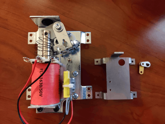
Left is an off-the-shelf flipper bracket, right is my mini bracket
It’s not perfect (in fact I can’t even mount the mechanics to it because I screwed up hole placements) but raising the flipper mechanics off the wood will allow me to place the fasteners I need under the mech.
Going FAST
For my earlier tests, I was just using an Arduino with a relay shield to control my solenoids. That worked for simpler mechs but my flippers require PWM so I needed a better solution. Around that time, FAST Pinball’s boards were back in stock so I picked up a Neuron, smart power filter board, I/O board, and some opto boards. These should give me just enough I/O to run my playfield’s lower-third. Even better, this means I can finally start using Mission Pinball Framework for my game rules instead of writing temporary C++ programs.
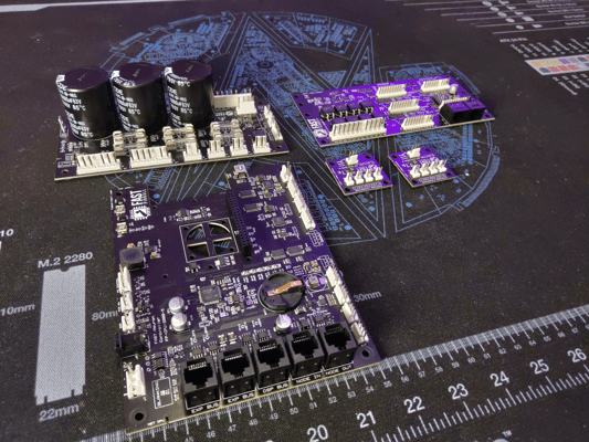
Hopefully all these boards will fit into the final cabinet without too much trouble
Burn it all down
With all this progress, you might be surprised to hear that I need to redo most of it.
Up till now, I’ve been using 6mm MDF for the playfield. I knew MDF wouldn’t work as a long-term solution so my plan was to eventually switch to 6mm Baltic birch plywood for the final playfield; however, I’ve been rethinking that decision for some time. I just don’t think that 6mm birch will be enough to withstand the weight of all the mechs or offer enough material for the screws to hold onto.
After putting it all together, I’ve made the painful decision to redesign the machine to use 1/2" Baltic birch plywood instead… which means the flipper, auto-plunger, ball trough, ball ejector, and slingshot all need to be redesigned. It’s painful but I think having more material to mount mechs into will pay off in the long run.