A fiberoptic DMD?! | Half Scale Pinball
Projects:
…but why
You, being a sane and reasonable individual, are probably wondering how I could possibly think it was a good idea to build a fiberoptic panel for my pinball machine’s DMD. Frankly, I don’t even have a great answer to that so I’m going to mix things up this post and just present this whole ordeal in the order of events that led me here. I realize I went pretty far off the rails with this one so bear with me.
Design requirements
This all started when I got thinking what kind of display I wanted for the machine. While pinball has used many display types over the years, I wanted a display capable of showing bitmap animations which left me with two options: a dot-matrix display (DMD) or an OLED/LCD screen.
System Shock is fairly low resolution by modern standards so I felt the look of larger pixels would suit it better and while I knew it was possible to emulate the look of a DMD on a screen, I still preferred the look of a real DMD’s rounded pixels. So problem solved, right? Just buy a small DMD and… this is where things started to get messy.
Most pinball DMDs have an aspect ratio of 4:1 with a resolution of 128x32 pixels. Modern DMDs are typically constructed from two 64x32 pixel modules commonly used for digital signage. Unfortunately, these off-the-shelf modules are not, to my knowledge, available in pitches less than 2mm (pitch being the center-to-center distance of each pixel). That may seem small on paper but consider that a 128x32 display with a 2mm pitch would still be 256mmx64mm (~10"x2.5"). Again, that may seem small but my entire backbox is only 14" wide and I still have to fit speakers on either side of the display. Not to mention a full size display is just 320mmx80mm (~12.6x3.1") so it’s not even that much smaller. Clearly, I needed to find a better solution.
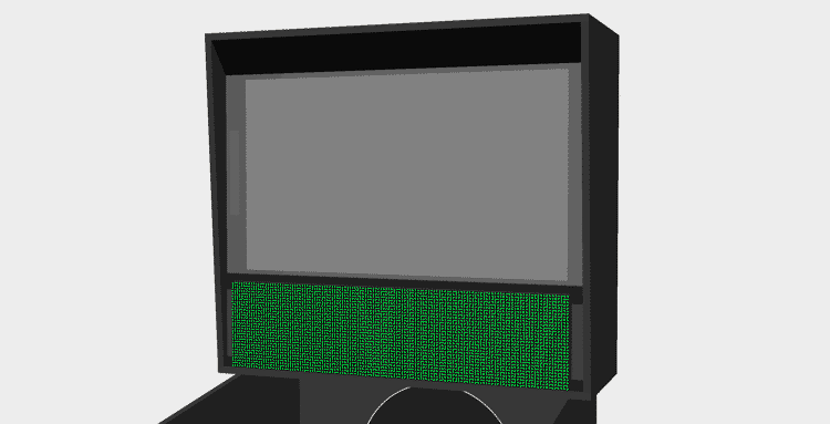
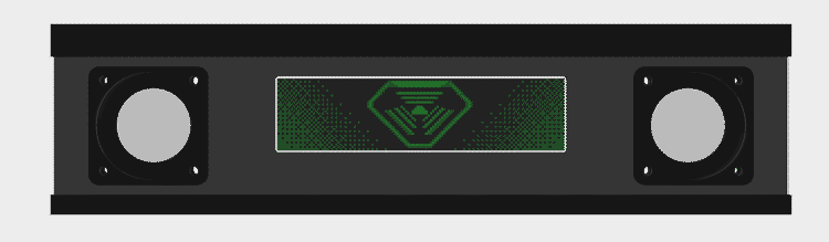
A full size display technically fits but something tells me the game wouldn't sound quite right without its front speakers!
Half resolution panel
The “obvious” next question was: since everything else on the machine is half-scale, why not halve the DMD resolution as well? On paper, this solved a lot of problems since a display with exactly half the resolution would fit perfectly in a half-scale backbox; however, as is often the case, ideas that sound good on paper don’t always work so well in practice.
The fundamental problem with this approach is that a pinball’s DMD already has a soul-crushingly small resolution of just 128x32. Aurich on Pinside already did a great job explaining why this resolution is so limiting so I won’t rant about it here but just looking at the image below should make it clear just how little information you can fit in this resolution with any semblance of theming.
Even on a full resolution DMD, the TriOptimum logo from System Shock barely fits
Now halve that already small display to just 64x16 (a resolution barely larger than some Tamagotchi models) and you’re left with something unusable for the kinds of animations I want (more on those later).

The font used throughout System Shock's levels is barely recognizable at a 64x16 resolution
Custom panels
If I had to pick a moment where things really started to spiral out of control, it would be here. Hellbent on not using a screen, this is where I checked my sanity at the door and started down the path of building a custom DMD.
8x8 matrices
The first idea that came to mind was to buy a bunch of 8x8 pixel matrices and arrange them into a custom display. The problems with this approach became apparent right away though as I couldn’t find anybody selling these matrices in a size anywhere near small enough. Just using the bog-standard size, I would only be able to achieve a resolution of 32x8.
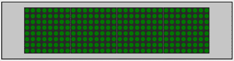
The black outline represents the size of a half-scale DMD. Unfortunately, these 8x8 matrices are so big that only four fit in the space.
Through-hole matrix
Since prebuilt panels were too big, I figured I could just wire up a panel from scratch using through-hole LEDs. I had seen a video a while back from Ben Heck about the custom DMD he built for his Bill Paxton machine which gave me confidence this would work; however, I soon learned the smallest through-hole LEDs I could get (1.8mm) were still too big. Upon re-watching Ben’s video, I also realized his matrix wasn’t the full resolution so I lost confidence that I’d even be able to wire a full resolution display manually.
Surface-mount matrix
Since through-hole LEDs were too big, I turned my attention to SMD LEDs. There are a few different sizes of SMD LEDs but the smallest I could find were so called “NanoPoint LEDs” at a size of just 0.65mmx0.35mm. But wait, didn’t I just say I couldn’t manually solder the 4096 LEDs my panel would require? Yes; however, my plan was to have the LEDs pre-installed on a custom PCB through a service like PCBWay. That is at least until I totaled up the cost. The LEDs alone would be over $500 plus another $300-400 for automated assembly. I’m not opposed to shelling out money for this project but nearly $1k for a display is just wasteful!
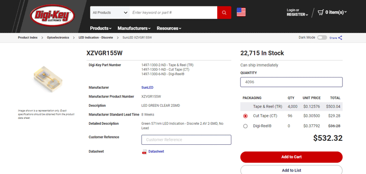
The cost of 128x32 (4096) NanoPoint LEDs from DigiKey
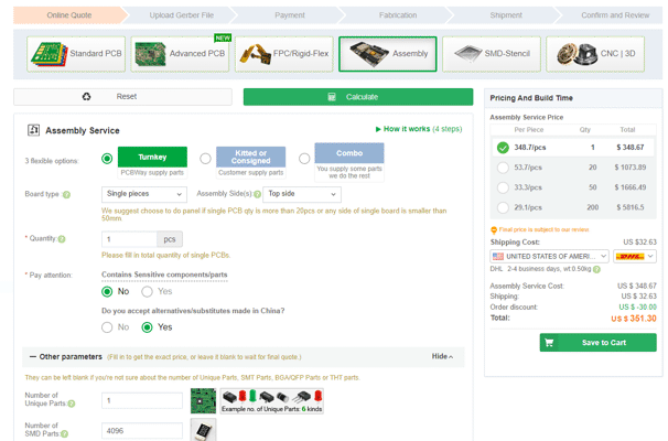
The cost to have PCBWay assemble a board with 4096 SMD components
Cost wasn’t even the main issue with this approach. Regardless of LED size, there are still physical limits on how close I can pack them on a PCB and still be able to route their power and ground traces. There may have been a way to make it work but I don’t have the PCB design experience (or any for that matter) to pull it off.
Fiberoptics
Of all the issues I mentioned above, one problem was common to them all: the physical limitation of how closely LEDs can be packed together. This got me thinking… if I can’t fit the LEDs any tighter, could I instead route the light from a larger panel to a smaller display? I briefly considered using lenses but that idea was soon squashed by another: fiberoptics.
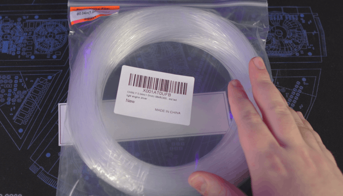
Bundles of fiberoptic filament like this are readily available on Amazon in many different lengths and diameters
I did some quick searching to see if anyone else had attempted something similar and sure enough two others had already uploaded videos of their designs: elliotmade and Dr. Tõnis Gadgets. With that validation, this seemed like a good idea; however, I couldn’t decide on how to build the display. My two thoughts were to either use a larger diameter filament and simply pack the filaments together for larger pixels or to use a smaller diameter filament and build a grid to space the dots out (like what the YouTubers had done). For testing, I decided to use one of the 8x8 matrices I bought earlier to prototype each approach.
Packed filaments
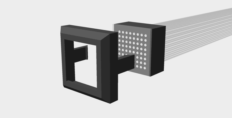
My plan for the “packed filament” approach was to build a square frame which would hold the filaments tightly together. I hoped the filaments would naturally arrange themselves into an 8x8 grid if there was no free space to go anywhere else. I was concerned some filaments, particularly in the middle of the matrix, would end up closer or further back and thus darker than others so I also built a bezel which would hold a thin piece of polycarbonate to the frame acting both as a display surface and a hard stop to push the filaments to. For this test, I chose to use 1.5mm filament as this was the largest I could go without a 128x32 display becoming too big.
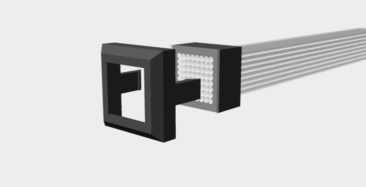
Exploded view of the assembly
On the LED side, I simply created a part which would snap onto the 8x8 matrix and allow the fibers to be press-fit into holes over each LED. I wanted to ensure the light from one LED couldn’t travel to a different fiber so I designed the part to fit flush against the panel but recess the fibers back to minimize light polution.
Note how the filaments don't go all the way through the mount. My thought being this would help prevent light bleed.
Unfortunately, the problems with this design were severe enough I couldn’t even test it. Right away, I found the filament did not fit into the frame I designed. I thought at first the filament was either larger than advertised or my printer undersized the part; however, neither of these were the problem. The issue turned out to be the filament, which hard been shipped as a roll, was trying to remain curved and thus taking up more space. I found I could just barely fit the filaments into the frame if I applied enough force but in doing so the filaments were not aligning into a grid like I had hoped and were instead forcing the frame apart leaving gaps in the display.
Despite my best efforts, I couldn't get the filaments to align into a grid
I probably could fix this with enough time and patience but seeing as how I was already encountering issues in an 8x8 display, I felt it best not to attempt with a larger panel.
Spaced filaments
For my second test, I borrowed most of the design from the previous experiment but changed the frame to be a solid piece with a grid of holes. I used 1mm filament for this test and initially designed the part with a hole pitch of 1.5mm to result in the same size display as the previous experiment.
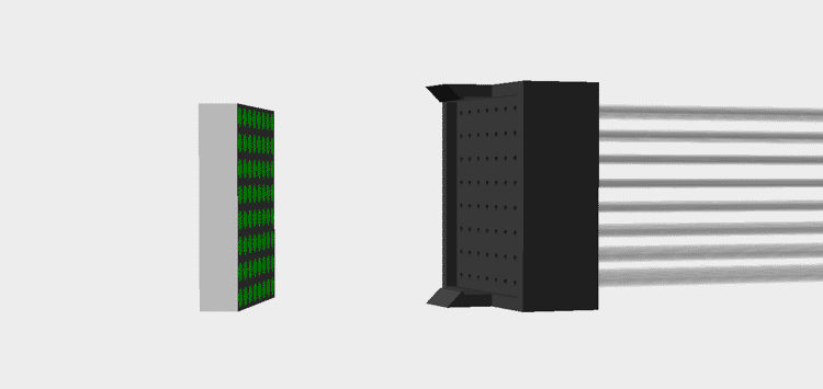
Exploded view of the assembly
This didn’t work out as planned either though. My printer has a 0.4mm nozzle and despite my best efforts there just wasn’t any way I could slice the part and have it come out correctly at this resolution.
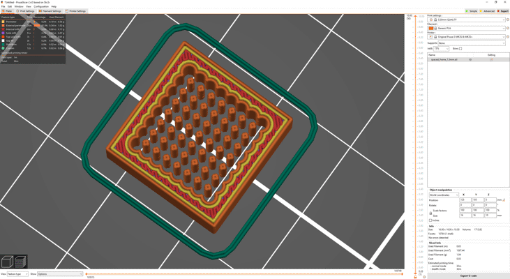
With some tinkering, it was possible to get the slicer to accurately slice the thin walls; however, my printer just couldn't handle it
In desperation, I tried increasing the hole pitch to 1.9mm and reducing the final resolution to only 100x25 dots to maintain a similar size. Thankfully, this did slice without error but my problems weren’t over yet. The holes in the frame came out inconsistent. Some were too large and others too small. Rather than spend an eternity tweaking the hole sizes and slicer settings, I felt it would be best to just drill out all the holes to 1.5mm and glue the filaments in place.
This was a mistake.
It took me four days of gluing to finally complete the display. Not only did I have to wait a couple hours between each row to allow the glue to dry (accelerant couldn’t reach the glue inside the holes) but it took ages to find which filament needed to go where. I knew I didn’t technically need to line the filaments up on the DMD and display sides since any mismatch could be corrected in software but I’m not a fan of fixing hardware problems in software.
While the display face may look messy from the glue, I suspect some window tint could hide the marks without significantly affecting the lights
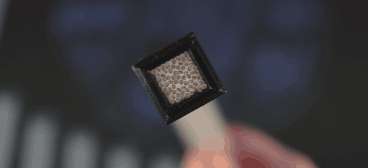
The final assembly was done and to my delight it actually worked quite well save for two problems. The first being some filaments pulled out slightly from the frame while drying resulting in a few pixels which are noticeably darker than others. This could probably have been fixed with more QC but the second problem was more fundamental.
While obvious, the dark pixel isn't the only problem here. Look closely and you'll notice there is a fair bit of light bleed to adjacent pixels.
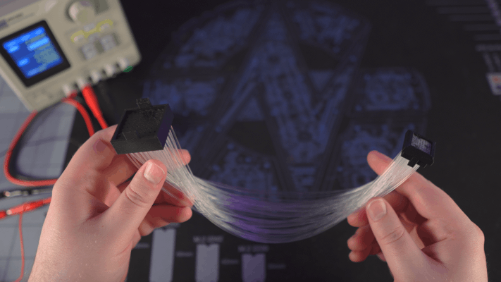
I had completely overlooked that a bundle of the filament would no longer be flexible so the two ends of the display could not be moved. What’s more, the curve of the filaments forced the assembly to contort into a curve as well making it much harder to work with. Like most issues I described, there is almost certainly a way to get around this in the final machine but at this point I was exhausted, defeated, and was frankly bored of this who endeavor.
Compromise
While none of the approaches I tested worked, I don’t feel the time was wasted. I learned a fair bit along the way and I’m sure I can find some other uses for the fiberoptics in the future. That said, I still need a display.
I decided to finally do the reasonable thing and resolve to just use an OLED panel but I still wasn’t happy with how how emulated DMDs look. I got to thinking though… what if I had the display render square pixels and just put a mask over the screen to make them round.
The pixels look a bit off here since the mask is raised above the surface of the screen
Frankly, I’m embarrassed I didn’t think of this sooner. It seems so obvious in hindsight. I thought at first the mask layer might be hard to manufacture given the hole size and spacing but I got an online quote to machine it from metal for around $350. That’s certainly not cheap but it’s not completely unreasonable either. I do have a couple other ideas though. I figure I could try with vinyl; although, I worry it will be difficult to apply without distorting. I’m also curious if a blank PCB would work given PCB routing is typically very precise and quite cheap.
256x64 panel
That just leaves one last problem, the OLED panel.
I’m usually skeptical of panels advertised for use with Arduino and Raspberry PI boards as they’re often controlled via slow interfaces that limit the refresh rate; however, I did find a 256x64px OLED panel with options for a parallel interface and even natively supports 16 levels of greyscale per-pixel (though I only plan to use 4).
Like the other pre-made displays I mentioned earlier in this post, the only problem with this model is it’s size… except in this case it’s a bit too small. The pixels of this display are only 0.53mm so the entire display is just ~135x34mm (~5.3"x1.3"). That’s a fair bit smaller than the 160mmx40mm (~6.3"x1.6") of a true half-scale display and the 192mmx48mm (~7.5"x1.9") size I was aiming for with the fiberoptic panels. Even with the speakers on either side, I think this panel would look a bit too small; although, I may get one to try out anyways.
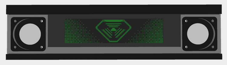
What do you think of the square speaker grills? They're still a work in progress but I'm worried they make it look like the front-end of a jeep.
High resolution panel
Another option would be to just buy a replacement panel for a phone, tablet, or similar and find a controller to drive it. I believe this would be the cheapest option by far given mobile displays are a commodity; however, finding one wide enough to fill out the space without being too tall will be a challenge. There is also no guarantee that I’ll be able to find a display driver capable of running it.
With some searching, I eventually found another promising option. 8.8" (~223mm) 1920x480 displays are apparently common in automotive applications and you can even buy some that natively accept HDMI. Size is once again a problem here though as the 217mmx54mm (8.5"x2.1") area is a bit bigger than I’d like. I could hide the extra pixels behind the bezel but it encroaches on the speakers at that point.
With this X-ray, you can see just how much of the screen would be cropped and why the speakers have to be moved to accommodate it
Animation sneak peek
Ultimately, I’m going to put more display testing aside for a bit and focus on other parts of the machine. That said, I want to leave you with some ideas I’ve been working on for potential DMD animations.
Disclaimer: None of these images are final. I don’t claim to be great with pixel art so I may even commission someone to remake them later.
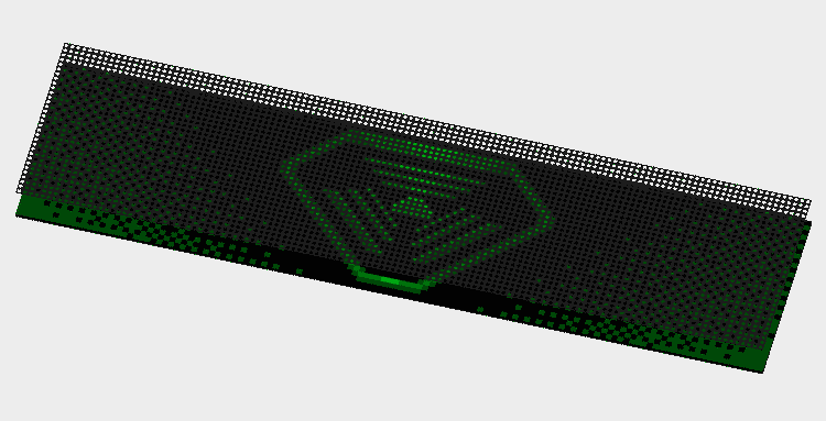
TriOptimum Logo
The TriOptimum logo I’ve shown throughout this post is meant to be part of the attract mode. My intent is to periodically play a DMD-rendition of System Shock’s opening video. The green text of the hacker’s laptop is a big part of the reason I want a green DMD.
The gradients are just here to fill in space in the screenshot. They won't be there in the final animation.
Fonts
System Shock makes use of several different fonts; however, my favorite is the retro-futuristic font, StopD, used to label each floor of the station. I plan on using this font for any large text in the game. Interestingly, System Shock uses a customized variant of the font (or perhaps an older version) as some letters differ slightly (for example, the Y). For this reason, I’ve gone through screenshots of the game painstakingly re-creating their version of the font pixel-by-pixel.

I couldn't find an example of a W in System Shock's levels so this one is based on the original StopD font. More tweaking is needed to make it match the style of the others.
SHODAN
One of the creepiest occurrences in the original System Shock is how SHODAN’s face will periodically fade into view on displays showing static. I’ve always loved that detail and thought it would be cool if I could do something similar on the DMD. I think the effect works best when the player just barely catches it so my plan is to have the face rarely fade in behind the player’s score but dissappear before they have a chance to get a good look at it.
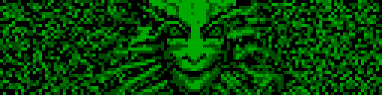
In game, SHODAN appears to have a wide smile on the in-game displays; however, I'm fairly certain this is just a side-effect of down-sampling her usual stoic expression to the lower resolution displays. Either way, I like how creepy her smile looks and decided to mimic it for my game.
CAD Files
By the way, I’ve published STLs to Printables and the CAD to GitHub if you really want to try making one of these fiberoptic displays as well; although, I really can’t recommend it for anything more than an experiment.