Replacement Score Camwheels
How it all started
About a year ago, Joe’s Classic Video Games uploaded a video showcasing a cracked Chicago Coin score camwheel and their workaround to fix it. They mentioned how these camwheels crack over time and that nobody makes replacement parts for them. I didn’t think much about it at the time but more recently they uploaded another video talking about the same problem and how there are still no replacements. The workaround they used is relatively well known and does seem to hold up well, but this time I got to thinking how many machines have camwheels that are damaged beyond repair or have been salvaged from other machines over the years.
While I don’t own the vintage machines using these camwheels (or any for that matter), I do value preservation of old hardware and software so I decided to try and create models for these parts so others can maintain their machines. Actually, my original goal was to both re-create the original design as well as redesigning the camwheels to be more robust; although, I ultimately dropped the redesign efforts for reasons I’ll get into later.
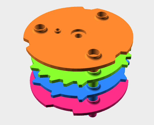
The completed cams. Those in the know may notice the cams are in the wrong order
Reverse engineering the dimensions
I checked online but unfortunately, nobody was selling any of the camwheels and without them it would be difficult to determine their correct dimensions. Thankfully though I was able to determine a few key dimensions from the videos I mentioned earlier. With those dimensions and a ton of screenshots from a number of different games, I went into image editing software to determine the remainder of the dimensions. It helped that Chicago Coin was a US company and appeared to primarily use fractions of inches for their dimensions making it easier to pinpoint the size from pictures.
I actually made a lot of good progress estimating the dimensions this way but there were a few I still wasn’t quite sure about. I could take a guess and release the models as-is but I wanted to be a little more sure before making them public. Thankfully, a Vintage Arcade Preservation Society (VAPS) and Pinside member, Deverezieaux, offered to help as they had already been using a 3D printed camwheel in their Sound Stage machine. The model Deverezieaux is using was created in conjunction with cerebral3d (ArtStation & Twitch) and with some luck they were able to find the old file and send it over. It’s a good thing they did too…
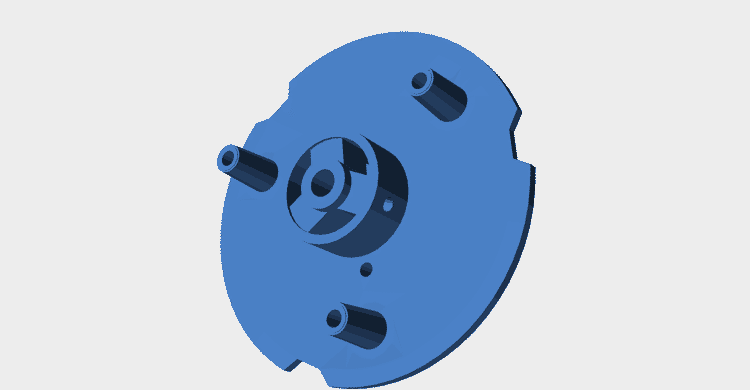
The camwheel model provided by Deverezieaux and cerebral3d
Their model confirmed a lot of assumptions I had made but it also confused me. The model had recesses I hadn’t seen in any pictures and it didn’t appear to match any of the known measurements I had found online. It was at this time I realized I made a mistake. I assumed all of Chicago Coin’s machines used the same camwheels since they all appeared similar but I now realized they changed the size of their camwheels at some point and my measurements were based on pictures from incompatible models.
Since I now had a known working model of the 190-517-X camwheel to reference, I decided it was best to put aside the dimensions I had been working on and instead focus on creating models for the 190-518-X, 190-548-X, and 190-620-X camwheels. I chose to make these specific models because I have seen from pictures online that they are the same size as the 190-517-X and I was able to find good technical drawings of their cam placements on IPDB.
Something’s still not quite right
As I was nearing completion of the camwheels, I realized something wasn’t quite right. The model I received from Deverezieaux had a recess in the back of the camwheel and a matching protrusion on each wheel’s shaft collar so I assumed these were meant to fit together; however, I noticed the protrusion on the shaft collar wouldn’t slot into the recess because the three support posts were the same length as the protrusion but did not have matching recesses.
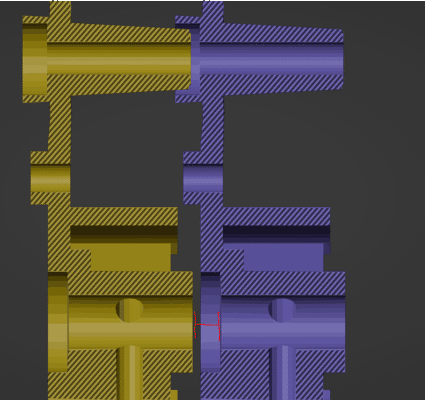
This X-Ray view of two original camwheel models showcases the problem. Notice how the support post is nearly flush with the next camwheel but the central support hasn't even reached its recess yet.
After confirming with Deverezieaux that the protrusion on the shaft collar was meant to fit into the back of the next I decided the best course of action would be to just add recesses for the support posts. Honestly, I’m not completely confident my approach is correct but without having an actual camwheel on hand to confirm I think this is the safest bet. Worst case scenario is someone does print a camwheel, finds out it’s not correct, and I update the CAD. It’s more inconvenient than anything else.
Data structures in OpenSCAD
I wanted to make the camwheels configurable but the software engineer in me didn’t like having tons of global variables or modules with 34+ parameters. When writing traditional code, I’d typically be inclined to create a configuration class to group large groups of parameters but OpenSCAD has no concept of classes; however, it does have lists.
With previous projects, I’ve tried creating rudimentary data structures to store my configuration values. My approach was to simply create a list and store each configuration value at a known index; although, I never really liked that model for a few reasons. Firstly, this approach is pain to add/remove parameters from as OpenSCAD doesn’t allow you to directly set the elements at an index. Related, you can only access the configuration objects by array index. Even if you do create wrapper functions to abstract the exact parameter index, you are still forced to manually update the indices in those wrappers to keep them in sync with the array.
// Create an LED specification using a helper function
LED_3MM = create_led_spec(
    body_diameter = 3,
    total_height = 5.3,
    base_diameter = 3.8,
    base_height = 0.81,
    lead_pitch = 2.54,
    lead_diameter = 0.5
);

// Helper function to create an LED specification list
function create_led_spec(
    body_diameter,
    total_height,
    base_diameter,
    base_height,
    lead_pitch,
    lead_diameter) = [
      body_diameter,
      total_height,
      base_diameter,
      base_height,
      lead_pitch,
      lead_diameter
    ];

// Abstractions to fetch various arguments from an LED specification list
function led_body_diameter(specification) = specification[0];
function led_total_height(specification) = specification[1];
function led_base_diameter(specification) = specification[2];
function led_base_height(specification) = specification[3];
function led_lead_pitch(specification) = specification[4];
function led_lead_diameter(specification) = specification[5];

// Module to create an LED from a specification
module led(specification) {
  body_diameter = led_body_diameter(specification);
  total_height = led_total_height(specification);
  base_diameter = led_base_diameter(specification);
  base_height = led_base_height(specification);
  lead_pitch = led_lead_pitch(specification);
  lead_diameter = led_lead_diameter(specification);

  body_radius = body_diameter / 2;
  base_radius = max((base_diameter / 2), body_radius);
  ...
}
Notice how any change to the create_led_spec function’s array will require changing the indices of the functions below it.
What I really wanted was something like a map/dictionary data structure where I could store key-value pairs but OpenSCAD doesn’t have anything like that… or does it? While it’s true OpenSCAD doesn’t have any map-like data structures, I learned it does include a nifty search function which can find the index of an element in a list. On the surface, this doesn’t seem like it would help until you realize that this function can also search nested lists. Thanks to dipi on StackOverflow for pointing this out detail.
With this, I could now store key-value pairs as lists inside a larger list then lookup those values by searching for the index of the element whose nested list contained the desired key. As an added bonus, having the parameter names in the specification list now also means that I can print the list to the console to see all of the named parameters when debugging.
// Helper functions to get any parameter's argument from a specification
function get_specification_parameter_index(specification, parameter_name) =
    search([parameter_name], specification)[0];
function get_spec_argument(specification, parameter_name) =
    specification[get_specification_parameter_index(specification, parameter_name)][1];

// The names of each parameter in the specification. I personally prefer functions over global
// variables.
function led_spec_body_diameter_parameter_name() = "body_diameter";
function led_spec_total_height() = "total_height";
function led_spec_base_diameter() = "base_diameter";
function led_spec_base_height() = "base_height";
function led_spec_lead_pitch() = "lead_pitch";
function led_spec_lead_diameter() = "lead_diameter";

// Helper function to create an LED specification
function create_score_camwheel_specification(
    body_diameter,
    total_height,
    base_diameter,
    base_height,
    lead_pitch,
    lead_diameter) = [
  [led_spec_body_diameter_parameter_name(), body_diameter],
  [led_spec_total_height(), total_height],
  [led_spec_base_diameter(), base_diameter],
  [led_spec_base_height(), base_height],
  [led_spec_lead_pitch(), lead_pitch],
  [led_spec_lead_diameter(), lead_diameter]
];

// Module to create an LED from a specification
module led(specification) {
  body_diameter = get_spec_argument(specification, led_spec_body_diameter_parameter_name());
  total_height = get_spec_argument(specification, led_spec_total_height());
  base_diameter = get_spec_argument(specification, led_spec_base_diameter());
  base_height = get_spec_argument(specification, led_spec_base_height());
  lead_pitch = get_spec_argument(specification, led_spec_lead_pitch());
  lead_diameter = get_spec_argument(specification, led_spec_lead_diameter());

  body_radius = body_diameter / 2;
  base_radius = max((base_diameter / 2), body_radius);
  ...
}
Is this approach way more verbose? Yes, absolutely. Is it easier to maintain? Also, yes. For simple examples like this, the extra overhead probably isn’t worth it but I really like the assurances it gives me when working on parts with many more options.
Enhanced camwheels
When I first set out on this project, I had the intent on redesigning the camwheels to be more robust. Why? Well there were two problems with the original design that I felt I could fix. Firstly, the shaft collar of the wheel is prone to cracking from its set screw being overly tightened into the aging plastic. Second, the cams will wear over time and eventually become too short to close the switches. I felt I could fix these issues by redesigning the camwheels to use a metal shaft collar and by having the main cams be machined from metal. Ultimately though, both enhancements were dropped.
For the shaft collar, my plan was to simply buy an off-the-shelf flanged shaft collar and attach it to the model. Unfortunately, I later discovered that while such shaft collars are readily available in any metric size, I couldn’t find any online retailer selling the imperial size required for the score motor’s shaft. I thought about just using the closest metric size but decided against it for fear of it creating too much wobble.
I knew there would be no off-the-shelf metal part suitable for the camwheel but I found it wouldn’t have been that expensive to get one custom made from an online machine shop (around $30 or so). I could have proceeded with this plan but I decided it wasn’t worth it after talking to Deverezieaux. You see, they had printed their replacement camwheel back in 2017 and reported it was still working fine so I figured a metal replacement just wouldn’t be worth the effort.
All that said, I did make one crucial enhancement to the original camwheel’s design. The original wheel has protrusions on both the top and bottom making it difficult to print without excessive support material. From what I could tell, the protrusions on the bottom weren’t actually needed so I included an option in the CAD to remove them thus making one side of the part flat and easier to print. Not the fanciest tweak but sometimes the simpler things are the most worthwhile.
Custom camwheels
From the start, I knew my camwheels wouldn’t be perfect given I didn’t have a reference so I wanted to make the CAD easily customizable for others could add in more accurate measures later. I had intended to just upload a SCAD file to Thingiverse so people could customize the models directly in their browser; although, I found the models simply had too many polygons for Thingiverse’s customizer plugin to handle.
I still wanted the models to be easy to customize without prior CAD knowledge so I put together a template file explaining what all the different parameters did and how to set them. I also added a model viewer scad file with customizer settings to view each model and adjust the level of detail.
You may be wondering why I didn’t just make all the model’s parameters adjustable in OpenSCAD’s customizer. I had wanted to do this but decided against it for two reasons:
- I wanted users to have control over the parameters of each cam on the wheel and customizer has no support for a variable number of parameters to support this.
- With the template file, users can choose whether to use inches or millimeters. Customizer options have no (easy) way of supporting different units of scale.
As I mentioned earlier, the camwheels I created only fit later Chicago Coin machines. I have other projects I want to get back to and don’t have time to finish determining the measurements for the older camwheels. Since the earlier camwheels seem to follow the same basic shape, my hope is that making the models easily customizable will allow others to continue where I left off and create custom wheels to match the older designs.
Where to get the files
With all that said and done, I’m happy to say the four camwheel models are complete and available for download at Printables. The CAD files are also available in GitHub. If you run into any compatibility issues with these models, please let me know by logging an issue to the GitHub repo.