Ball Trough | Half Scale Pinball
Projects:
It’s working! (finally)
I know it’s been a while since my last post but I have a good reason… Borderlands 2 is a lot longer than I remembered. No but seriously I’ve actually made a lot good progress since my last post and now have a working ball trough, ejector, and auto-plunger to show for it.
My hope was to complete prototypes of the ball trough, slingshots, flippers, auto-plunger, and lanes so that my next post could feature them all working together. Obviously, that didn’t happen. I kept running into problems here and there that pushed a full test out. A few of the problems still aren’t fully resolved but I felt it was best to show what I have now before waiting for everything to be final.
So what problems remain? I’m sure you didn’t ask but I’m going to tell you anyways:
- The current flipper design is bulky and likely to fall apart after moderate use
- The auto-plunger needs to operate at 24v which means I need to redesign the flippers to work at that voltage as well
- I designed for lane walls that were only 1/8" thick and I’m realizing now they’re too thin to screw into from the edge for mounting
I’ll talk more about those issues toward the end but for now let’s think positive and talk about that fancy new ball trough.
Design process
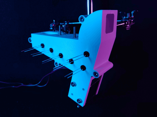
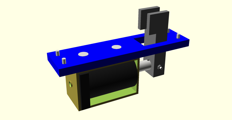
The ball trough assembly in all its vaporwavey goodness
This is actually the third iteration of the ball trough design. The original plan was to model the ball trough and ejector as one piece but make the ejector chute/scoop a separate component. I eventually realized there was no reason the two components couldn’t be combined for easier assembly.
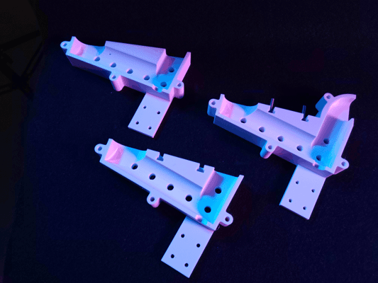
The progression of trough designs from first (left), second (bottom), to current (right)
I also revised the playfield mounts in the second and third revisions. The first revision had heat-set inserts pressed into the top with the intent being to bolt into them through the playfield. While this would have worked at first, I was concerned the heat-sets would work their way out over time. This wouldn’t have been a concern if I had pressed the heat-sets in from the bottom of the part but there was no easy way to do that without compromising functionality. An easier fix was to just switch which side had the nut and which had the bolt. The new design features T-slots allowing four M3 hex bolts to be held captive in the assembly. The threads of these bolts pass through the playfield from the bottom and the whole assembly is secured from the other side using washers and lock nuts.
That’s not to say heat-sets have no place in this design though. The final revision added heat-sets to one half of the assembly and counterbores to the other allowing the two halves to be bolted together more securely and without protrusions on either side. This was done to give me more clearance for the circuit boards later (more on that in a bit). During final assembly I intend to use thread locker on the heat-sets to ensure the bolts can’t back out from vibration (being careful of course to not get any on the plastic).
Updated solenoid
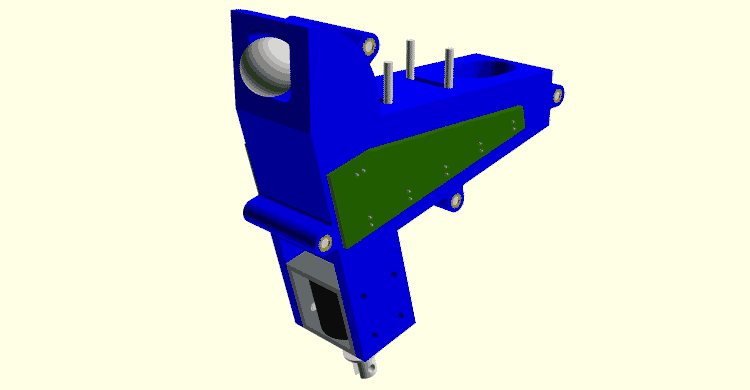
You don't want to know how long it took to render this image thanks to all the hacky Boolean operations I used to model it
Something that may not be obvious from the pictures is I’m no longer using the McMaster-Carr 70155K121 solenoid I tested back in February. While the 70155K121 was strong and much smaller than the first solenoid I tested, I managed to overlook one critical detail. The plunger on that solenoid was so long that it would have stuck out the bottom of the machine by half an inch.
Let this be a lesson to check dimensions in CAD before committing to a design 🤦♂️
Silly mistakes aside, the ball ejector is now using the much cheaper T Tulead ADD06190484. I don’t know why I never thought to check Amazon for solenoids before but this model is cheaper, stronger, and smaller than any solenoid I previously tested. At only 12v, this model is perfectly capable of ejecting balls from the trough even when all 5 balls are loaded or when two become jammed in the ejector chute.
Speaking of jams…
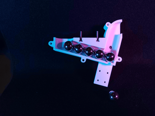
Behind each ball is a hole for an infrared LED. The opposing side of the assembly has matching holes for photodiodes.
Just like it’s larger counterparts, my design uses five pairs of infrared LEDs and photoelectric diodes to detect how many balls are currently in the trough. The LED and diode pairs form an invisible beam at each ball position that is broken when a ball sits between them. The software simply needs to count how many photodiodes are blocked to determine how many balls are in reserve.
If a ball ever fails to eject or otherwise falls back into the chute, there is a good chance that it will become stacked on the next ball in the trough. An additional LED/diode pair is placed in the ejector chute to detect this condition. When this photodiode is blocked for more than a few hundred milliseconds, the software knows a malfunction has occurred and can either attempt to unjam itself or enter maintenance mode.
For the moment, I’m just hooking up jumper wires to the sensor pairs for testing. I would have liked to use proto-board; however, the LEDs are spaced 5/8" apart (the ball diameter) so the spacing doesn’t quite line up for standard pitch PCBs. Once the machine is nearing completion, I’ll send off for custom PCBs; additionally, I’ll add holes to the model for M2 heat-sets to mount the boards to.
WIP Auto-plunger
I'm not planning on adding a manual plunger to the System Shock pinball machine but I've designed the kicker arm to allow for one in future projects.
I created a rough working prototype of the auto-plunger but there is one big issue with the design. The kicker arm is only attached to the solenoid plunger using an M2 nut and bolt. While I could make the nut captive, the bolt will likely still become loose over time. I’d like to use a clevis pin instead; however, the smallest clevis pin I can find is 3mm in diameter but the hole in the plunger is closer to 2.8mm. I could try widening the hole but I’d rather just find a new solenoid model that’s more compatible and potentially smaller.
One thing I like about this design and have started incorporating into other mechs is how the solenoid is mounted. Screwing into the solenoid through the bracket does make replacing the solenoid more difficult but it makes for a much more stable mount. As an additional bonus, having the bolts held captive between the playfield and bracket ensures they can never work themselves loose even without thread locker.
If you’re familiar with how auto-plungers are designed for full-size machines you may have noticed there is no room for a kicker ball sensor with the solenoid mounted directly under the playfield. I didn’t have room on the right side of the shooter lane for an optical sensor either and I’d like to avoid capacitive sensors as I don’t like the look of sensor plates or conductive tape. I also considered making the kicker arm out of two insulated conductive plates and using the ball to complete a circuit between them but I decided to avoid custom metal parts for the moment. Ultimately, I’ve chosen to just use an inductive probe. Beneath the apron is a LJ8A3-2-Z/BY probe that pokes through the left shooter lane. With correct placement, I’ve found this probe to be very reliable at detecting when the ball settles on the kicker arm.
Revisiting the flipper
It's not easy to spot in the first picture but the flipper shaft passes through a precision flanged PTFE bushing just like it would on a full-sized machine
I’ve had a working flipper design since before I started this blog; however, experience designing other mechs and changes to the machine as a whole have made me rethink this design. For starters, the current design is unnecessarily bulky. This is largely due to the body being interchangeable between the right and left flipper assemblies; however, part of the bulk is due to the solenoid being mounted sideways and could be trimmed down by using the same mounting technique as the auto-plunger.
Parts availability and tooling is also somewhat of an issue. It’s not pictured above but the flipper bat and crank are reinforced by a 4mmx4mmx50mm shaft made of steel bar stock. The only 4mm bar stock I could find was made of hardened tool steel and wasn’t available in the length I needed. I was able to cut one shaft down to size with great difficulty but that’s not an endeavor I ever want to repeat. I’m currently investigating the options Misumi has for ordering custom rotary shafts as they look to have all the features I need (albeit at an eyewatering price).
Similar to my concern with the auto-plunger, I’m not happy with the linkage being attached using M2 nuts and bolts. Unlike the auto-plunger, the nut and bolt head are held captive; however, they do still become loose after a few shots. Switching to clevis pins should solve this issue but requires that I use a solenoid with a wide-enough hole to accommodate the pins I have in addition to making the linkage parts wider.
I also want to remove the skate bearing for simplicity sake. The bearing serves two purposes in the current design 1) to stabilize the crank shaft and 2) to prevent the crank body from sliding off the steel bar running through it. I don’t think I actually need the bearing to stabilize the shaft given it is already constrained by a fairly long precision PTFE bushing in the playfield; furthermore, the crank sliding off shouldn’t be a problem if I add a set screw.
This design isn’t all bad though. I was initially very worried that I wouldn’t be able to find flipper rubber in the right size or with many color options. As luck would have it, “Grifiti Band Joe” silicone bands ended up being the perfect size and came in several different colors. Newer prints of the flipper also include a rubber backstop to prevent damage to the linkage when the flipper resets.
Next steps
Once the flipper redesign is complete I’ll send off for a laser-cut playfield for an integration test. I also need to replace the relays in my prototype with MOSFETs so I can PWM the coils.
Just to level-set, all that’s a bit of a ways off though as I’m working on some upgrades to my 3D printer to support ABS printing and those upgrades will have it out of commission for a time. I also want the first full integration test to be well recorded so I’ll be spending longer than usual on its video.