Testing Inductive Probes | Half Scale Pinball
Projects:
Background
One of the goals for my half-scale System Shock pinball machine is to include fully-functioning slingshots. For those unfamiliar, slingshots are the triangular kickers located just above the flippers on most pinball machines. The slingshots are designed to kick the ball diagonally up or down the playfield on contact.
This video shows a great closeup of a slingshot in action if you’ve never seen one before:
Designing half-scale slingshots that can kick was actually pretty easy; however, finding a reliable way to trigger them was a whole other problem. On a full-sized machine, the slingshots are triggered by two leaf switches located just behind the rubber ring. The slingshot is activated when the ball deflects the ring causing it to close one or both of the switches. This mechanism works great for an ~80g (~2.8oz) pinball but not so well when scaled down. Even with the softest rubber rings I could find to fit my slingshots (75A), the measly 16.3g (0.57oz) ball I’m designing for just can’t deflect the rubber far enough or with enough force to actuate most physical switches.
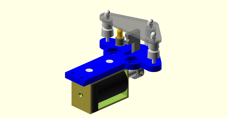
My current slingshot design for reference
To put the problem into perspective, the Gateron Clear keyswitch is one of the lightest keyboard switches you can buy at the time of writing with an operating force of just ~0.3N (0.06lb). Even with such a light switch, I would have to stack two of the 5/8" (~15.87mm) chrome steel mini pinballs just to operate it (let alone bottom it out) with the measly 0.16N (0.03lb) of force each exerts under gravity. Obviously, pinballs are going to be subject to more forces than just gravity and you can find a handful of other physical switches with lower operating forces; however, switches with such low operating forces often require excessive actuation distances or are too sensitive to vibration to use in close proximity to solenoids. I do know of one physical switch that can be reliably activated by the mini pinballs; however, that’s a topic for another day and it won’t work in this context anyway.
As I mentioned in my first post, physical switches are far from the only option for detecting the mini pinballs. Ultrasonic, infrared, and capacitive among others are all good candidates but for this post I will focus on inductive sensors. I specifically want to investigate the use of standard industrial inductive probes like you’d find on a 3D printer.
The Probes
There are plenty of inductive probes available from electronics suppliers but I chose to limit testing to two specific models: LJ8A3-2-Z/BY and LJ18A3-8-Z/BX. Why? The main features I like about these models are they’re easy to mount, trivial to interface with, and have flexible voltage ranges. It also helps they happened to show up on Amazon while I was browsing other parts. The main differences between the models are their size and maximum detection range. The LJ8A3-2-Z/BY advertises a range of only 2mm while the LJ18A3-8-Z/BX boasts an 8mm range at the expense of a much larger footprint.
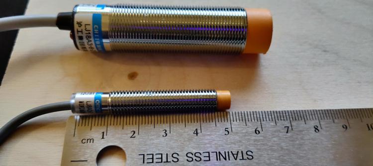
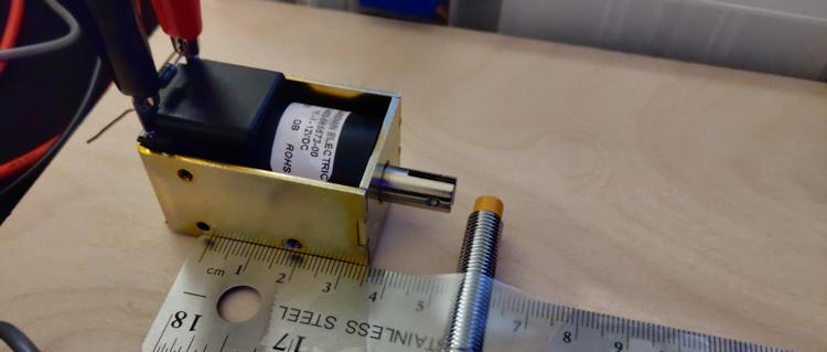
Size comparison of the LJ8A3-2-Z/BY (bottom) and the LJ18A3-8-Z/BX (top)
Both sensors connect using only three wires: power (brown), ground (blue), and signal (black). Questionable wire coloring aside, both sensors are rated for an input voltage of 6-36v and will output a signal when metal is detected in front of the orange cap (or lack thereof in the case of the LJ18A3-8-Z/BX). The maximum range at which the sensors trigger is fixed regardless of the input voltage or at least that’s what the manufacturer claims…
Curiously, I discovered by mistake that running the probes below their rated voltages can nearly double the detection range in some cases. For example, running the LJ8A3-2-Z/BY at only 4v resulted in it consistently triggering at 4mm instead of the claimed 2mm. Unsurprisingly, there is a consequence to running these probes out of spec but it’s worth the tradeoff in my opinion and something I’ll discuss later in this post. I couldn’t tell you if this behavior is common to all inductive probes but I’ve found it to be incredibly helpful and is the main reason I’m writing this post.
Testing Detection Range
Knowing the detection range of each probe changes with voltage, I wanted to run tests to measure the extent of this affect; furthermore, I wanted to measure how far the mini pinball would have to pass over sensor before it was detected.
For testing, I first printed test jigs to align each probe and ball to the same height and let me slide the sensor closer to the ball along a ruler at various horizontal offsets from the ball. I then placed the ball at a known position along the ruler. For each combination of sensor, input voltage, and horizontal offset I would slide the sensor toward the ball until my multimeter showed the sensor had triggered. I would repeat the test a few times to verify consistency then record the distance between the edge of the ball and tip of the sensor.
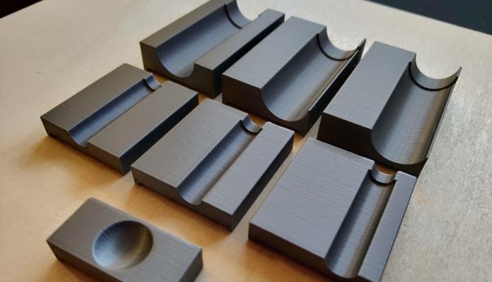
The test jigs
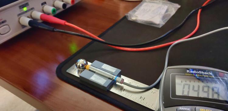
The sensor range test setup
Each sensor was tested at its lowest stable voltage, 5v, and 12v. I opted to not test at any higher voltages as I’m expecting to have power supply rails for 5v and 12v in the final machine but the only rail I’m planning with higher voltage is for driving coils and I don’t think it wise to run sensitive electronics off the same rail.
Each sensor was tested at three horizontal offsets:
- (A) Ball center aligned to the sensor cap’s center (no offset)
- (B) Ball center aligned to the edge of the sensor cap
- (C) Ball edge aligned to the sensor cap’s center
LJ8A3-2-Z/BY
4v was the lowest I could reliably operate this probe. At 3v, the sensor would trigger but not stop once metal left its detection area.
| Sensor Voltage (v) | Horizontal Offset (mm) | Max Detection Distance (mm) |
|---|---|---|
| 4 | 0.00 (A) | 4.0 |
| 4 | 3.25 (B) | 3.5 |
| 4 | 7.94 (C) | 1.0 |
| 5 | 0.00 (A) | 2.0 |
| 5 | 3.25 (B) | 1.0 |
| 5 | 7.94 (C) | - |
| 12 | 0.00 (A) | 2.0 |
| 12 | 3.25 (B) | 0.5 |
| 12 | 7.94 (C) | - |
LJ18A3-8-Z/BX
5v was the lowest I could reliably operate this sensor. The sensor would not trigger at lower voltages.
| Sensor Voltage (v) | Horizontal Offset (mm) | Max Detection Distance (mm) |
|---|---|---|
| 5 | 0.00 (A) | 7.0 |
| 5 | 7.94 (C) | 4.5 |
| 5 | 8.25 (B) | 4.5 |
| 12 | 0.00 (A) | 6.0 |
| 12 | 7.94 (C) | 3.5 |
| 12 | 8.25 (B) | 3.0 |
Testing the Effects of Solenoid Interference
While prototyping the slingshot, I found activating a solenoid close to a probe would cause the probe to trigger. This wasn’t really concerning for the slingshot assembly on its own since I could just ignore the false activation in code but I was worried nearby unrelated probes might also trigger.
To test just how far away a probe would need to be to avoid interface, I first taped each probe to a known position on my ruler. I then placed my test solenoid (model A420-065573-00) along the ruler and fired it at different voltages while watching the probe’s output. If the probe falsely triggered, I would move it half a millimeter away and repeat until it no longer triggered. I repeated this test using the same probe voltages as my previous test and with three different solenoid voltages as I haven’t yet decided the final voltage for the game. Furthermore, I ran this test both with the solenoid facing the probe and with it beside the probe to determine how much the orientation mattered.
Interference test setup (face)
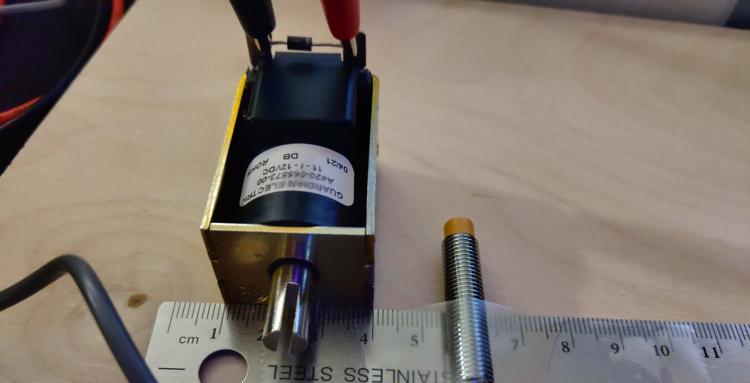
Interference test setup (side)
For each probe voltage, solenoid voltage, and solenoid orientation, I recorded the maximum distance I found interface as well as the minimum distance I found the probe to be clear of interface. The distance measurements were taken from the faceplate of the solenoid to the center of the probe and from the side plate of the solenoid to the center of the probe.
Hyphens in the following tables indicate configurations were I was unable to get the probe to falsely trigger even when directly touching the side of the probe to the solenoid.
LJ8A3-2-Z/BY
| Sensor Voltage (v) | Solenoid Voltage (v) | Max Face Interference Distance (mm) | Min Face Clear Distance (mm) | Max Side Interference Distance (mm) | Min Side Clear Distance (mm) |
|---|---|---|---|---|---|
| 4 | 12 | 2.0 | 2.5 | 1.0 | 1.5 |
| 4 | 15 | 3.0 | 3.5 | - | - |
| 4 | 18 | 3.5 | 4.0 | - | - |
| 5 | 12 | 1.5 | 2.0 | - | - |
| 5 | 15 | 1.5 | 2.0 | - | - |
| 5 | 18 | 1.5 | 2.0 | - | - |
| 12 | 12 | - | - | - | - |
| 12 | 15 | - | - | - | - |
| 12 | 18 | - | - | - | - |
LJ18A3-8-Z/BX
| Sensor Voltage (v) | Solenoid Voltage (v) | Max Face Interference Distance (mm) | Min Face Clear Distance (mm) | Max Side Interference Distance (mm) | Min Side Clear Distance (mm) |
|---|---|---|---|---|---|
| 5 | 12 | - | - | - | - |
| 5 | 15 | - | - | 1.0 | 1.5 |
| 5 | 18 | - | - | 1.0 | 1.5 |
| 12 | 12 | - | - | - | - |
| 12 | 15 | - | - | - | - |
| 12 | 18 | - | - | - | - |
Results
Ultimately, these tests have given me confidence that undervolting my sensors won’t be a major issue. The increased range (especially for the LJ8A3-2-Z/BY) is extremely valuable and I don’t expect it to be difficult to keep probes more than 4mm away from other assembly’s solenoids to avoid interface. I did find it interesting though that neither probe could be falsely triggered when run at 12v. This leads me to believe the probes are only susceptible to interference when run outside their rated voltage; although, I admittedly didn’t test within the lower end of their specifications.
All that said, the range of the probes is still a concern. Something to consider is these probes are too long to be mounted on top of the playfield which means they’ll have to be mounted under it. Even the best probe configuration I tested can still only detect up to 7mm but my playfield is already 1/4" (6.35mm) thick and that’s excluding the vinyl artwork. I could drill holes into the playfield and mount the sensors flush with its surface; however, it would be difficult to get a close enough fit to not cause the ball to jump when passing over.
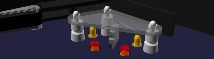
The slingshot design with inset sensors. The wider hole is necessary to accommodate the probes' threads. The red cylinders represents the detection area.
This problem bothered me for a few days but I think I finally landed on a decent solution. By overlaying the playfield with a thin sheet of stiff polycarbonate 1/32" (~0.8mm), I can freely drill holes for the sensors in the wood layer while keeping the plastic play surface smooth. This solution comes with a few fringe benefits as well. Applying the playfield graphic under the plastic will help to protect it from the ball in much the same way Mylar film is used to protect full sized machines. This also allows me to hide the sensors if I attach the artwork to the back of the plastic rather than the wood.
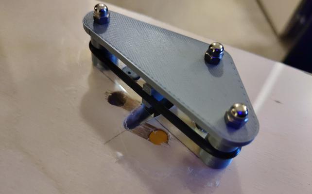
If it weren't for the reflection, you'd hardly know there was a plastic layer here. You'll have to excuse the tape and jagged holes. This prototype has been through a lot of iterations and poorly measured cuts.
Next Steps
I worry the sensors may still not have a wide enough radius to detect the ball reliably in game; however, I won’t know for sure until I finish the lower-third and can start play testing. If you’re not familiar, the lower-third is the literal lower 1/3rd of the playfield and includes the major assemblies: flippers, slingshots, the shooter lane, drain, and in/out lanes. I already have working prototype flippers and rough designs for the drain and shooter so next up are the lanes.